Review Article - Imaging in Medicine (2011) Volume 3, Issue 5
Radiological assessment of shoulder instability
A Mistry1 & AP Toms†11Department of Radiology, Norfolk & Norwich University Hospital, Colney Lane, Norwich, Norfolk NR4 7UY, UK
- Corresponding Author:
- AP Toms
Department of Radiology
Norfolk & Norwich University Hospital
Colney Lane, Norwich, Norfolk NR4 7UY, UK
Tel: +44 1603 286 104
Fax: +44 1603 286 077
E-mail: andoni.toms@nnuh.nhs.uk
Abstract
Shoulder instability is a common problem, defined as symptomatic motion of the glenohumeral joint that can present as pain or a sense of displacement. There are a multitude of lesions/injuries associated with shoulder instability, many of which are further subdivided or subclassified. This causes much confusion, that is not helped by the various acronyms used to name the abnormalities. Arthrographic imaging methods are commonly used to delineate these, in particular MR arthrography. This article attempts to address these lesions/injuries in a logical and practical approach with emphasis on the anatomy and key imaging findings that influence surgical management.
Keywords
instability ▪ MR arthrography ▪ MR imaging ▪ shoulder
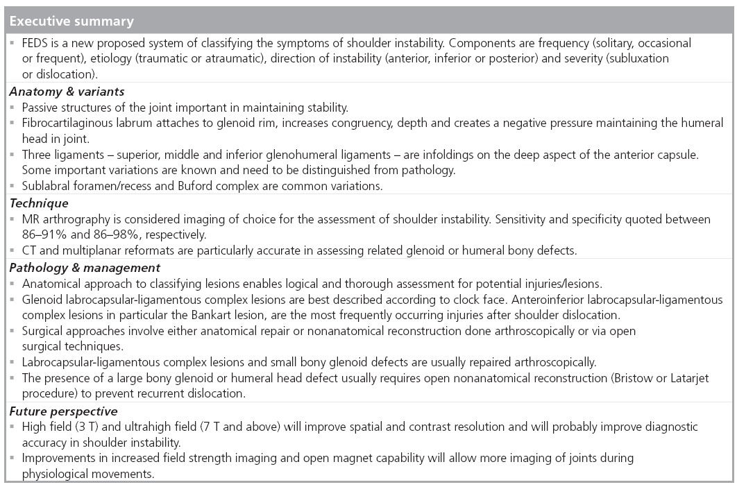
Shoulder instability is a common problem which is defined as symptomatic motion of the glenohumeral joint, which can present as pain or sense of displacement [1]. There are several systems of classification in the literature of shoulder instability. Recently, to introduce some consensus, the FEDS system has been proposed [2]. The symptoms are classified according to Frequency (solitary, occasional or frequent), Etiology (traumatic or atraumatic), Direction of instability (anterior, inferior or posterior) and the Severity, based on subluxation or dislocation.
The etiology of shoulder instability is likely multifactorial. Though trauma is the most common cause, repetitive or habitual use and structural or congenital factors contribute in varying degrees. Advances in arthroscopy and radiological imaging have revealed a variety of lesions associated with shoulder instability. Confusing acronyms are often used in practice and in the literature to describe many of these abnormalities.
The objectives of this review are to facilitate the understanding of the relevant anatomy and anatomical variations, discuss the imaging techniques used to assess the unstable shoulder, describe the various pathologies whilst attempting to clarify some of the confusing terminology and discuss the key imaging findings that influence clinical management.
Relevant anatomy & variants
The glenohumeral joint is a complex ball and socket joint with anatomy arranged to favor maximum mobility and function over stability. As a result it is the most common major joint to dislocate or become unstable.
Stability of the glenohumeral joint is achieved through active and passive mechanisms. Active structures comprise the long head of biceps (LHB) tendon and the rotator cuff structures. The description of the active structures will not be discussed, as it is debatable whether injury/pathology results in, or is a consequence of, instability [3]. The muscles around the shoulder girdle can be strengthened to improve the stability of the joint to a degree [4]. Passive structures of the joint include the bony glenoid, labrum, capsule and glenohumeral ligaments. The labrocapsular ligamentous complex (LCLC) is the functional unit comprising the fibroligamentous soft tissue structures, see Figure 1.

Figure 1: The anatomical arrangement of the rotator cuff tendons (SS, IS
and Sub), glenoid labrum and capsuloligamentous structures.
IS: Infraspinatus; SS: Supraspinatus; Sub: Subscapularis.
The bony glenoid is oval in shape and lined with hyaline cartilage. The fibrocartilaginous labrum attached to the glenoid rim, increases the depth of what is otherwise a shallow articulation. The labrum may also provide stability through negative pressure, effectively creating a vacuum resisting distracting force. On axial imaging, the predominant labral shape is triangular, but a number of variations have been demonstrated. Other frequently encountered shapes are round, cleaved or notched edges [5].
The anterosuperior labrum is commonly variable. It may be focally detached or there may be fenestration in the labrum itself, referred to as a sublabral recess or foramen, see Figures 2 & 3. The labrum in some cases may be absent [6]. The Buford complex occurs when there is association of any of these variations along with a thickened, cord-like middle glenohumeral ligament (MGHL), see Figure 4. On axial MRI an absent anterosuperior labrum with a thick MGHL close to the glenoid margin may easily be mistaken for a labral tear. A thick MGHL on oblique sagittal images will help discriminate this variation [7,8].

Figure 2: Schematic illustrating the position of a sublabral foramen and an example T2 axial oblique image showing the communication of fluid through a defect in the anterosuperior labrum.

Figure 3: Schematic and axial oblique short TI inversion recovery view of a sublabral recess.

Figure 4: Schematic and short TI inversion recovery images at two levels illustrating the Buford complex. Thickened cord-like middle glenohumeral ligament with deficient anterior labrum.
The fibrous capsule is reinforced on its superficial aspect by the musculotendinous units of the rotator cuff. There are three infoldings on the anterior deep aspect of the capsule. These are identified as the superior, middle and inferior glenohumeral ligaments. The superior glenohumeral ligament (SGHL) extends from its origin on the superior glenoid margin, located immediately anterior to the origin of the LHB, attaching distally to the lesser tuberosity of the humerus. Here it is closely located to and partly blends with the coracohumeral ligament. The SGHL is best demonstrated on axial images, where it is seen directly beneath, or next to, the proximal LHB. Variants include a common origin with the biceps tendon, alone or with the middle glenohumeral ligament [9]. Of the glenohumeral ligaments, the SGHL is probably the key stabilizer when the shoulder is adducted. It is much less of a stabilizer when the joint is abducted.
The middle glenohumeral ligament is the most variable of the three ligaments. It may be underdeveloped or absent in up to 30% of shoulders, in such cases the SGHL may be noted to be thicker [10]. The MGHL inserts with the subscapularis tendon to the base of the lesser tuberosity or it may merge into the subscapularis tendon distally, see Figure 5. There are three variable proximal attachments of the MGHL. Type 1, the most common, attaches to the tip of the labrum or blends with the labrum. Type 2 attaches to the glenoid rim periosteum a few millimeters from the labral base and type 3 originates from the scapular neck. These different types are best assessed with joint distension as part of an MRA study. MGHL is an important stabilizer with the joint at a 45° abduction and during external rotation [9].

Figure 5: Axial oblique short TI inversion recovery image from an MRA study shows a normal anterior labrum and middle glenohumeral ligament.
There are two main parts to the inferior glenohumeral ligament (IGHL), the anterior and posterior bands, although anatomical variations are common. Between these bands is a sling that forms an inferior recess or axillary pouch. The anterior and posterior bands attach to the inferior glenoid rim, see Figure 6. Distally, the ligament forms a collar-like insertion slightly inferior to the articular edge of the humeral head. The anterior band is usually thicker than the posterior band but the converse can also occur [7]. The IGHL is the primary stabilizer with the joint abducted past 60° [9].

Figure 6: Short TI inversion recovery images from MRA studies illustrating the inferior glenohumeral ligament. (A) Sagittal oblique image showing the sling-like attachment to the inferior rim of the humerus. (B) Axial oblique of the inferior glenohumeral ligament and (C) sagittal oblique image indicating the anterior and posterior bands at its origin.
Technique
MRI and MRA are the main techniques by which the shoulder joint is assessed for causes of instability. Plain radiography, ultrasound, CT and CTA are other methods, each with their own merits and limitations.
Plain radiography is usually employed in the context of acute trauma. Various views can be obtained but the most common are anteroposterior (AP), axillary and transcapular or Y-view. Acutely, the shoulder can be confirmed within joint or assessed for any associated fractures of the glenoid or humeral head. Glenoid or humeral bony defects (Bankart or Hill–Sachs, respectively) may be shown on AP or axillary views but a study by Madler et al. found the sensitivity of standard views were 45% for Hill–Sachs defects and 37% for bony Bankart defects [11]. Anteroinferior bony defects of the glenoid are best shown on a West Point axillary view where the sensitivity can be improved [12]. Performed with the patient lying prone and the affected shoulder resting on a pad, the beam is aimed 25° from the horizontal plane and 25° toward the patient’s midline [13]. Information from plain radiography of the shoulder in a traumatic instability is limited. Signs of rotator cuff tear arthropathy (diminished acromiohumeral distance with impingement syndromes and arthritic changes of the glenohumeral joint) may be shown but cannot provide any predictive information on the clinical status of the patient [14,15].
The role of ultrasound in the assessment of shoulder instability is limited to excluding other concomitant injuries, particularly rotator cuff tears. It is operator dependent and has limited imaging of the labrum. CT has excellent bone resolution and, therefore, is more sensitive than plain radiography. Subtle fractures, complex fractures, bone defects or loose bodies are easily and accurately assessed [16]. Multidetector CT technology and multiplanar reformat capability allow fracture planes to be fully assessed [17]. In patients with claustrophobia or other medical contraindications for MRI, CTA can be used instead of MRA. Soft tissue detail will be reduced, compared with MRI and MRA. Recent data suggests that a 16 slice CTA can perform as well as 1.5T MRA in the diagnosis of common shoulder instability problems, such as Bankart, Hill–Sachs, rotator cuff and superior labral anterior to posterior (SLAP) lesions [18]. Also a retrospective review of 43 CTA studies with arthroscopic correlation by Zappia et al. found for anteroinferior labroligamentouscapsular lesions, the sensitivity, specificity and accuracy were 89–92%, 86% and 88–91% respectively [19]. It is, however, limited in the assessment of partial tears, extent of edema and marrow abnormalities. Radiation dose also limits the utility of the modality, particularly important in young athletes.
MRA is considered the imaging modality of choice and numerous studies have shown that MRA is more sensitive than conventional MRI in the assessment of LCLC abnormalities. Sensitivity and specificity for shoulder instability are quoted between 86–91% and 86–98% [20–25].
MRA sequences commonly used include spin echo T1-weighted with frequency-selective fat suppression obtained for the three planes of the scapula. A fluid-sensitive sequence allows detection of bone marrow edema and fluid collections. The shoulder is positioned in neutral position with a dedicated shoulder coil. For some lesions, such as the Perthes lesion (see later), putting the ligaments under strain in abduction and external rotation (ABER) can help to reveal subtle abnormalities.
For arthrographic studies access to the joint space can be obtained with fluoroscopic guidance. This could be via an anterior and posterior approach. Some radiologists recommend the approach is modified according to the overall direction of instability in order to reduce the possibility of introducing confounding findings on the symptomatic side. Therefore, for anterior instability a posterior intra-articular injection is suggested and vice versa [26,27]. Access to the joint has also been described using ultrasound and CT guidance [27,28].
Pathology & management
There are many ways of describing the lesions associated with instability, more often based on the direction of instability. A combined management and anatomical approach enables categorization more usefully. Over the last decade the surgical management of shoulder instability has become less invasive and more elaborate with advanced arthroscopic techniques [29]. The surgical techniques can be broadly divided into direct anatomical and nonanatomical repairs. Direct anatomical repair involves restoring the normal anatomy, whereas nonanatomical techniques, such as the Bristow or Latarjet procedures, aim to prevent recurrent dislocations [30]. Direct anatomical repair is usually undertaken arthroscopically, aiming to restore the LCLC structure usually with suture anchors. Nonanatomical reconstruction is generally used to prevent complications of large glenoid or humeral bone defects by transferring a variable amount of the coracoid (Bristow technique uses the tip of the coracoid, whereas Latarjet procedure a larger piece of the coracoid) with its conjoint tendon and attaching it to the inferior glenoid, significantly altering the anatomical configuration to regain stability. Such bone osteotomy and transfer techniques usually require adequate exposure as achieved with open surgery. Also a capsular tightening procedure may be performed as part of the last arthroscopic step or as part of closure of open surgery depending on whether it is felt to have excessive laxity.
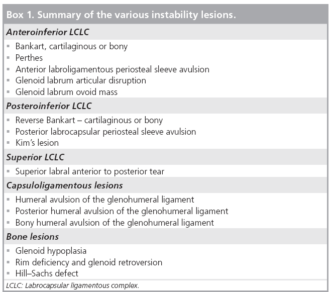
Anatomically, the lesions can be categorized into the region and structures affected. Many different injuries/lesions have been described in the literature, some further subcategorized or made complex with an array of acronyms. Essentially lesions can be soft tissue or bony, occurring on the glenoid or humeral side. The soft tissue structures that can be affected are the labrum, glenohumeral ligaments, joint capsule or articular cartilage. A particular injury may affect a single structure or combination of structures, see Box 1.
Glenoid LCLC lesions are easier to understand by referring to lesions according to positions on a clock face. The labrum is the surrounding rim of the clock face. 12 o’clock corresponds to the position of the biceps anchor. Immediately adjacent and anterior is the SGHL and at the 1 o’clock position the MGHL arises. The anterior and posterior bands of the IGHL approximately attach between the 5 and 7 o’clock positions, see Figure 7. Injuries occurring between 2 and 6 o’clock are referred to as anteroinferior lesions, 6–10 o’clock as posteroinferior and superior lesions primarily involve the 10–2 o’clock position. Humeral ligamentous capsular lesions occur either on the anterior or posterior sides.

Figure 7: Anteroinferior labrocapsular
ligamentous complex lesions occur
between 2 to 6 o’clock, posteroinferior
between 6 to 10 o’clock and superior
between 10 to 2 o’clock.
B: Biceps anchor; IGHL: Inferior glenohumeral
ligament; MGHL: Middle glenohumeral
ligament; SGHL: Superior
glenohumeral ligament.
Anteroinferior LCLC lesions
■ Bankart lesion
Originally reported by AS Blundell Bankart in 1923 [31], it was first described as separation of the fibrous capsule of the joint from its attachment to the fibrocartilaginous glenoid ligament. The description has evolved and is presently used to describe a LCLC detachment from the glenoid with rupture of the periosteum, specifically referred to as a fibrocartilaginous Bankart lesion. On axial MRA the anteroinferior labrum between 3 and 6 o’clock is separated from the glenoid. This part of the labrum, attached to the anterior band of the IGHL, is torn free from the scapula periosteum, see Figure 8. Interposed contrast or fluid lies between the separated structures and the labral fragment with its IGHL attachment lies free within the anterior capsular recess [20,32].

Figure 8: Example of a cartilaginous Bankart lesion. Anteroinferior labrum is torn free from the scapula periosteum. Contrast or fluid lies between the separated structures.
An osseous or bony Bankart lesion refers to a fragment of glenoid bone avulsion along with separation of the labroligamentous complex. The size of the fragment is variable and influences the surgical approach to treatment, see Figure 9.

Figure 9: Short TI inversion recovery axial oblique image from an MRA study showing a bony Bankart lesion. The scapula periosteum is torn and separated with a fragment of glenoid rim and labrum. The anterior band of the inferior glenohumeral ligament with the labral fragment lies free in the anterior capsular recess.
Waldt et al. in a retrospective study found MRA correctly identified Bankart lesions in 80% (35 out of 44) of cases [33]. Another study by van Grinsven et al. of 40 surgically confirmed cases, reported a sensitivity and specificity for MRA of 69 and 64%, respectively, in the assessment of fibrocartilaginous Bankart lesions [34]. CT with its superior bony detail is more sensitive than MRI for the assessment of bony Bankart lesions [35]. It is therefore not surprising that van Grinsven et al. found bony Bankart lesions assessed with MRA had a poor sensitivity of 25%, but when found were highly specific at 94%.
The Bankart lesion is the most common injury after first time anterior dislocations of the shoulder and is often the most frequent lesion found on imaging in the assessment of shoulder instability [33,36].
Fibrocartilaginous Bankart lesions are repaired arthroscopically using bioabsorbable sutures and depending on capsular laxity an inferior capsular shift procedure. A bony Bankart fragment of larger than 25% of the glenoid will require refixation or bone grafting (Figure 10) [37,38]. Recently two groups in France have further pushed the boundaries of arthroscopic surgery. They describe a Latarjet procedure and a combined arthroscopic coracoid transfer (Bristow–Latarjet) procedure and Bankart repair for anterior instability involving bone loss and labral injury [39,40]. The results of a series of 47 cases undergoing a combined procedure have been recently published. 88% of the cases had the entire procedure performed arthroscopically [41]. Long term results are not yet available.

Figure 10: CT and plain radiograph of a bony Bankart lesion before and after surgical repair. (A) Axial oblique CT image of a bony Bankart injury. Assessment of the bony fragment is more sensitive with multidetector CT. Large bony defects often require nonanatomical reconstruction as with a Latarjet procedure; shown on the axial plain radiograph image in (B). Screws fix the detached coracoid process onto the inferior glenoid.
Key imaging: 2 to 5 o’clock complete detachment of the LCLC from the glenoid and periosteal detachment. It is important to assess for avulsed bony component along with the labral detachment, if present, recording the size of osseous fragment. If borderline, CT may be required to accurately measure the osseous fragment.
There are various other anterior LCLC abnormalities occurring between the 2 to 5 o’clock position, often referred to as ‘Bankart variant’ lesions. They can be considered to represent a spectrum of damage to the LCLC. Sometimes, with complex injuries, it is not possible to neatly categorize them other than as a ‘Bankart type’ injury. There are a range of injuries which include labral irregularity, periosteal stripping and ultimately labral detachment from the scapula periosteum. This however, does not imply correlation with a specific event or severity of the mechanism of injury.
■ Perthes lesion
A Perthes lesion is a labroligamentous defect at a similar position to the Bankart lesion. The labrum is detached from the glenoid, but is held by intact scapula periosteum. The periosteum of the scapula may be stripped medially. The torn anterior labrum may be minimally displaced or remain in anatomical position, see Figure 11 [32].

Figure 11: Examples of Perthes lesion. (A) Perthes lesion. Axial oblique short TI inversion recovery images of an MRA study shows a
defect in the anteroinferior labrum that remains attached to the scapula periosteum. (B) T2 MRA image of a Perthes lesion in abduction
and external rotation.
Courtesy of R Bleakney (Mount Sinai Hospital-University Health Network, Toronto, Canada).
In a report of ten arthroscopically confirmed cases, Wischer et al. noted that the lesion was best depicted on MRA images obtained in axial and ABER positions [42]. The IGHL becomes taut and shows best the separation of the anterior labrum from the glenoid rim, which is otherwise in contact with the scapula periosteum. Contrast or fluid fills the gap and produces a high signal intensity cleft between the bony glenoid and anterior labrum. Wischer et al. showed that in half of cases the lesion was not identified on axial MR images alone, and only when combined with ABER position could seven of ten cases be seen.
Key imaging: Can be difficult to visualize, ABER position optimizes chances of identifying the lesion. There should be a high index of suspicion for this lesion with anterior instability symptoms when no apparent LCLC disruption is present.
■ Anterior labroligamentous periosteal sleeve avulsion
Anterior labroligamentous periosteal sleeve avulsion (ALPSA) refers to a tear in the anteroinferior labrum with an intact anterior scapular periosteum, see Figure 12. Compared to the Perthes lesion, there is a greater degree of disruption as the torn labroligamentous complex displaces inferomedially and rolls up like a sleeve on the scapular neck [43]. The IGHL is no longer firmly attached and so results in anterior instability.

Figure 12: Axial oblique short TI inversion recovery image of an MRA study shows an anterior labral periosteal sleeve avulsion. Injury occurs between the 3 and 5 o’clock position of the labrum. The scapula periosteum remains intact and the torn labroligamentous complex rolls up medially.
Axial MRA shows a deformed LCLC displaced medially with an intact periosteum. The labrum is displaced and hence absent on the glenoid rim. Contrast outlines a crease or cleft between the glenoid and nodular shaped fibrous tissue on the glenoid neck [32,33].
The lesion is common in patients with chronic instability. Surgically, the aim is to convert the lesion to a fibrocartilaginous Bankart (i.e., detaching the complex from the scapula periosteum followed by reattachment by Bankart repair) [43].
Key imaging: medially displaced anteroinferior lesion with an intact periosteum. If chronic, may appear as a thickened low signal mass on the scapula neck.
■ Glenolabral articular disruption
The glenolabral articular disruption lesion is a tear of the anteroinferior labrum in combination with an adjacent articular cartilage injury. The labral component is primarily superficial without capsuloperiosteal stripping. The IGHL anterior fibers remain attached to the labrum and glenoid and hence the lesion is not often associated with anterior instability [44,45]. The articular component ranges from superficial fibrillation to deep subchondral defects. MRA images may show contrast entering or outlining the clefts or irregularities in the cartilages, Figure 13. Similar disruption of the articular surface with a subtle labral tear have been described in the 7–9 o’clock position, termed posterior-glenolabral articular disruption lesion [46].

Figure 13: Axial oblique short TI inversion recovery image of an MRA study depicting a glenoid labrum articular disruption lesion. Superficial anteroinferior labral and articular cartilage irregularity.
Mechanism of injury is thought to involve direct impaction while the arm is abducted and externally rotated. The severity of this mechanism probably accounts for the degree of articular cartilage damage. Arthroscopic debridement of the labrum and articular cartilage defect has been proposed as the treatment of choice [44].
Key imaging: important to note the anteroinferior labrum is nondisplaced and both IGHL and periosteum are intact. Define the degree of articular surface damage.
■ Glenoid labrum ovoid mass
First described in 1991 on nonarthrographic MRI images, the glenoid labrum ovoid mass was felt to represent a torn labrum that has retracted [47]. It probably can occur after any of the anteroinferior injuries and likely represents fibrous mass of damaged labrum with or without the MGHL. It also represents an example of how not all labral injuries are easily and neatly classifiable. On MRI, there is a dark, rounded and often expanded appearance to the anterior labrum, see Figure 14. The lesion is often seen in patients with recurrent dislocations and often associated with instability due to the underlying labral injury.

Figure 14: Example of a glenoid labrum ovoid mass lesion on axial oblique short TI inversion recovery image from an MRA study.
Posteroinferior LCLC lesions
■ Reverse Bankart lesion
Like its anterior equivalent, there are fibrocartilaginous and bony reverse Bankart lesions (or posterior Bankart lesion). A fibrocartilaginous lesion involves the posteroinferior labrum (between 6 and 10 o’clock). There is detachment from the glenoid along with a complete tear of the scapula periosteum. The bony defect can range from an avulsion-type rim fracture to a large comminuted fracture that may malunite, see Figure 15 [46].

Figure 15: Short TI inversion recovery images of a reverse bony Bankart lesion shown in the axial oblique plane (A) and sagittal oblique plane (B).
Similar findings, to the classic Bankart lesion, are found on axial MRA. Depending on the degree of detachment, contrast will, on occasion, extend into the cleft and outline the medial aspect of the posterior glenoid neck [46,48].
A reverse Bankart lesion is often seen in patients with a history of traumatic posterior dislocation. Assessment of the degree of bony disruption helps preoperative planning. Though bony defects can be seen on MRA, CT has a high sensitivity and specificity of 93% and 78%, respectively [49].
Posterior labrocapsular periosteal sleeve avulsion
Posterior labrocapsular periosteal sleeve avulsion is equivalent to the anterior labral periosteal sleeve avulsion lesion. A periosteal sleeve is created by avulsion of the posterior scapular periosteum at its junction with the capsule and labrum [48].
Surgical management is also similar to its anterior counterpart in that it involves reduction of the periosteal sleeve and detachment in order to reattach the labrum [50].
■ Kim’s lesion
Kim’s lesion is an incomplete avulsion of the posteroinferior labrum, concealed by an apparently intact superficial portion [51]. A marginal crack may occur at the chondrolabral junction. The deep/intrasubstance detachment does not disrupt the scapula periosteum or posterior band of the IGHL and so are intact on MRA, effectively the lesion is equivalent to the anteroinferior Perthes lesion, see Figure 16. Although four types of Kim’s lesions are described arthroscopically, three of these have been described on MRA. Type I is separation of the labral fragment without displacement. Type II is incomplete avulsion (i.e., a marginal crack at the chondrolabral junction) and type III loss of labral contour, which on arthroscopy appears as chondrolabral erosion. A type III lesion on MRA could appear similar to a recently described probable variant termed a posteroinferior labral cleft [52]. Noted on CTA, this is a superficial indentation or cleft of the labrum seen most often along the 7–8 o’clock position and particularly found to occur more often in females.

Figure 16: Short TI inversion recovery axial oblique image demonstrating a Kim’s lesion. It is equivalent to the Perthes lesion, but involves the posterior labrum. Scapula periosteum remains intact.
The mechanism for a Kim’s lesion is thought to relate to posteroinferior directed forces on the labrum. Proposed arthroscopic management involves posterior labral repair and a capsular shift procedure [51].
Key imaging: important to note whether there is a potential Kim’s lesion, as unless the deep portion of the labrum is probed at arthrography the lesion can be missed. A labral irregularity at the 7–8 o’clock position could represent a posteroinferior labral cleft variant rather than a true type III lesion.
Superior lesions of the LCLC
■ Superior labral anterior to posterior tear
These are superior labral tears orientated in the anterior-to-posterior direction. Four types were described in 1990 by Snyder et al., descriptions based on arthroscopic findings [53]. Type 1 lesions are degenerative fraying of the superior glenoid labrum. Type 2 consists of an avulsion of the labral-bicipital complex from the superior glenoid. Type 3 are bucket handle tears with an intact biceps anchor, and type 4 are bucket handle tears with extension into the biceps tendon.
The sensitivity and specificity on MRA for SLAP types I-IV lesions is 82 and 98%, respectively [21]. Coronal oblique MRA images are particularly helpful when assessing SLAP tears. Type 1 lesions will show fraying of the free edge of the superior glenoid labrum. If contrast media is seen to extend into the superior glenoid labrum and biceps anchor then type 2 lesions should be suspected (Figure 17). A corresponding finding of separation from the glenoid rim on axial images may be present but this itself is not of high diagnostic value [54–56].

Figure 17: The SLAP type II and short TI inversion recovery images in the axial oblique (A) and coronal oblique planes (B).
It is important to distinguish a type 2 tear from a sublabral recess. Contrast extending medially with a smooth linear appearance between the superior labrum and glenoid rim is indicative of a sublabral foramen, whereas contrast extending superiorly and lateral into the superior labrum and biceps anchor is that of a type 2 SLAP tear [57].
SLAP 3 lesions are best assessed on coronal oblique sections. Contrast medium extends between the superior labrum and the preserved biceps anchor with a triangular segment or displaced superior glenoid labrum into the joint space. SLAP 4 lesions appear similar but include avulsion of the biceps anchor with extension of contrast into the biceps tendon best appreciated on axial, coronal oblique or sagittal oblique images, see Figure 18.

Figure 18: Schematic of superior labral anterior to posterior type IV lesion. Involvement of the biceps anchor is probably best visualized on the coronal oblique short TI inversion recovery images following the long head of biceps and looking for discontinuity at its anchor.
The classification of SLAP tears has been expanded through to 13 different subtypes. These are essentially combined lesions. Types 5 to 7 are combined lesions of SLAP type 2 with an anteroinferior LCLC injury and types 8 to 10 are variants of SLAP type 2 lesions with involvement of the posteroinferior labrum. Although the further subtypes potentially improve communication of SLAP lesions and facilitate research, the classification beyond the first four types does not tend to influence the treatment of SLAP lesions [58].
Possible causes of SLAP lesions include a fall onto an outstretched hand transmitting a compressive force to the shoulder, secondary to athletic repetitive overhead use or external abduction forces. Type 1 lesions generally do not require any intervention. Debridement procedures are sometimes performed to remove the free fragment for type 3 lesions. Types 2 and 4 are considered unstable lesions due to disruption of the biceps anchor and can also cause secondary impingement or rotator cuff tears. Type 2 and 4 lesions require reattachment to prevent instability and its associated secondary problems [21]. Types 5–10 SLAP lesions have more extensive labral injuries and so secure repair of the superior labral complex and additional repair of the anterior or posterior labrum and MGHL is advocated to regain stability [58].
Key imaging: important to assess the involvement of the biceps anchor in SLAP lesions. Also assess for an associated anteroinferior or posteroinferior LCLC lesion.
Capsuloligamentous lesions
■ Humeral avulsion of the glenohumeral ligament
Disruption of the inferior glenohumeral ligament occurring at the humeral attachment may involve either the anterior or posterior band. These are termed humeral avulsion of the glenohumeral ligament (HAGL) and posterior HAGL, respectively. These are less common causes of instability but if it does occur is most likely anterior [59]. HAGL can be either pure soft tissue injury or involve an avulsion fracture from the medial cortex of the humeral neck, termed a bony HAGL.
A HAGL lesion is located below the level of the subscapularis muscle in the inferior pouch of the shoulder. It is important on MRA to observe distended capsule to confidently identify this lesion. It is best seen on T1-weighted images in the coronal oblique and sagittal oblique planes. With capsular distension the normal U-shaped axillary pouch is J-shaped due to extravasation of fluid/contrast across the torn humeral attachment extending along the medial humeral neck, Figure 19. However, this finding is not specific, as reported by Melvin et al. of four false positive cases [60]. These cases were actually found to have Bankart lesions at arthroscopy that probably accounted for medially extravasated contrast.

Figure 19: Sagittal oblique short TI
inversion recovery image of an example of
a humeral avulsion of the glenohumeral
ligament lesion. There is loss of the normal
inferior axillary pouch due to injury of the
inferior glenohumeral ligament at its humeral
attachment.
Courtesy of R Bleakney (Mount Sinai Hospital-
University Health Network, Toronto).
The HAGL lesion is commonly seen among athletes particularly rugby players and is thought to result from hyperabduction and external rotation [8]. This lesion can be easily overlooked at arthroscopy unless specifically addressed. Treatment is by arthroscopic reattachment or closure of the IGHL defect.
Key imaging: distended capsule aids diagnosis. J-shaped axillary pouch of the IGHL with extravasated contrast extending medially provided no other labrocapsular lesion is demonstrated.
Bony abnormalities
Bony lesions associated with instability can be either congenital or secondary to trauma. Recurrent or habitual instability may make this distinction less clear and with certain abnormalities it can be difficult to decide if this is the cause or effect of recurrent instability. Management of bone abnormalities most often involves open surgery to perform nonanatomical Bristow–Latarjet type reconstructions, although complex arthroscopic techniques have recently been performed.
■ Glenoid hypoplasia
This is a congenital disorder with a spectrum of abnormality ranging from mild posterior rim deficiency to a poorly developed glenoid neck. It is thought to occur secondary to incomplete ossification of the lower two thirds of the glenoid and scapular neck. This result is a smooth articular surface of the glenoid and abnormal hypertrophied posterior labrum. It is commonly bilateral and symmetric [46,61]. MR shows tissue of heterogeneous signal intensity located in the hypoplastic region indicating a combination of fibrocartilage and fat replacing and compensating for the osseous hypoplasia [46]. CT would accurately identify the degree of bony involvement and MR will show the abnormally thickened labrum and/or associated tears.
Glenoid hypoplasia is often associated with multidirectional and posterior instability. Posterior labral tears are also often found. Patients tend to present in the 2nd or 3rd decades with bilateral symptoms and can present later in the 5th or 6th decades with severe degenerative joint disease. Treatment is posterior stabilization for instability and arthroplasty in severe cases of degenerative joint disease [62].
■ Rim deficiency & glenoid retroversion
Recurrent, atraumatic posterior shoulder instability has been shown to be associated with an osseous defect of the posteroinferior glenoid rim [63]. Two types of shape: the lazy J and the δ have been described. Normally the height of the posteroinferior part of the labrum is similar to that of the anterior part. Retroversion of the glenoid with loss of height and retroversion of the posteroinferior aspect of the labrum can lead to loss of containment of the humeral head [64]. This is a frequent finding in shoulders with atraumatic posterior shoulder instability. It is difficult to know if these are a cause or effect of instability. The favored view, however, is that recurrent posterior translation across the labrum causes flattening of the normal configuration and loss of height. Measurement of glenoid and labral version and loss of height can be made on axial T2-weighted images.
The proposed treatment for glenoid retroversion is capsulolabroplasty. This involves creating a full-thickness tear at the base of the posteroinferior labrum and then reattaching the labrum to the surface of the glenoid with capsular plication done arthroscopically. The aim being to restore the labral buttress and capsule tension [65].
■ Hill–Sachs defect
The Hill–Sachs and reverse Hill–Sachs defects are usually the result of traumatic anterior or posterior shoulder dislocation, respectively. A fracture results when the humeral head impacts on the glenoid rim, which can also be traumatized (Bankart or Bankart variant lesion may occur). The humeral defect can involve up to 30% of the articular surface. If significant, the anterior humeral defect, subsequent to a posterior dislocation, when internally rotated can catch onto the rim and cause further dislocation, termed an engaging Hill–Sachs lesion. This mechanism can also result in tear of the posterior labrum.
Plain radiography can show these humeral impaction fractures and they are best demonstrated on axial views. However, smaller lesions are better and reliably assessed on CT. Sagittal and axial plane measurements are more accurate than the coronal plane [66]. It is important to distinguish a subtle defect from the normal flattening of the humeral groove. Traumatic defects are usually located above the level of the coracoid process [9].
The engaging Hill–Sachs lesion is usually treated with an open surgical procedure. For defects up to 30%, a Bristow or Latarjet procedure can be used. For a defect greater than 30%, options include infraspinatus transfer, rotational osteotomy and osteochondral allograft. In lesions greater than 40%, arthroplasty should be considered [38,67].
Future perspective
3 Tesla (T) or high field strength MR imaging applied to the shoulder or other musculoskeletal joints has the potential to improve the visibility of the normal bone and soft tissue anatomy through an increase in signal-to-noise ratio and contrast-to-noise ratio. Applied to the glenoid labrum and articular cartilage it may improve the diagnostic capability of noninvasive MRI techniques. Although some researchers have found no significant difference in the sensitivity of high-field MRI compared to high field MRA, its advantage in resolution compared to imaging at 1.5 T field strength is likely to improve diagnostic accuracy [68,69]. It is unlikely that MRA techniques will be superseded in the near future by improvements in field strength and anatomical resolution, as physical separation of the injured fragments through joint distension is more likely to reveal subtle abnormalities, unless there is a significant joint effusion already present.
Further improvements in MR technology has led to development of ultra-high field strength MRI or capabilities of 7 T or more. Further improvement in signal-to-noise ratio and contrast- to-noise ratio will better delineate the anatomy. However, at higher field strengths there are issues with chemical shift artefacts, susceptibility artefacts, radiofrequency energy deposition, changes in relaxation times and problems with homogeneous radiofrequency coil design [70]. At higher field strengths imaging time is much faster than 1.5 T systems.
Researchers have, in the past, attempted to define the anatomical changes associated with movement. There are two main methods of studying joint movement, these are kinetic imaging and dynamic, or real time, imaging. Kinetic imaging primarily focuses on acquiring static images with incremental changes in joint position. The data is then reconstructed and cine-looped to assess changes in the anatomy with joint position. There are several studies which were performed primarily in the mid- 1990s describing their findings using this technique [71]. Although spatial resolution is good, there are a number of disadvantages. In narrow bore systems, which are most widely available, abduction movements cannot be assessed and also complex movements recreating symptoms, for example the throwing action, is virtually impossible. Internal and external rotation movements can be made but these are passive and the acquisition time is too long to be of any practical use. With the development of open configuration MR units, dynamic or realtime imaging of joints in an unrestricted way has been made possible. Vertically open units allow assessment of peripheral joints and spine in physiological weight-bearing positions and physicians are able to perform stress testing of joints within the MR unit [72–74]. Motion of the unrestricted joint is technically challenged with the requirement to continually adjust the scan plane according to position. MR tracking systems have been developed. One such method consists of a miniature RF coil immersed in a reservoir of gadolinium that is attached to the patient’s skin overlying the region of interest [75]. An ultrashort tracking MR pulse sequence in each x, y and z axis is applied, allowing positional information to be acquired and therefore, scan plane updated accordingly. This technique currently requires the movement to take place at slow speed to allow optimal function. It is also limited to a large field of view and thus reduced spatial resolution. With improved processing power, field strengths, coil design and better understanding and prediction of potential artefacts, dynamic or real time imaging of joints will gain more importance.
Conclusion
The imaging of shoulder instability has progressively become more complex with sub-classifications of various injury types and increasingly elaborate arthroscopic repair techniques. MR arthrography of the shoulder is the main modality used to diagnose injuries or lesions associated with instability. Understanding the anatomy of the structures contributing to stability and knowledge of the anatomical variants is key to diagnosis. It is also important to know the particular findings associated with lesions/injuries that influence surgical approach, to which the reading radiologist can add value. Improvements in the future of MR imaging with higher field strengths and imaging of the joint during physiological motion will no doubt further our knowledge and approach to management.
Financial & competing interests disclosure
The authors have no relevant affiliations or financial involvement with any organization or entity with a financial interest in or financial conflict with the subject matter or materials discussed in the manuscript. This includes employment, consultancies, honoraria, stock ownership or options, expert testimony, grants or patents received or pending, or royalties.
No writing assistance was utilized in the production of this manuscript.
References
Papers of special note have been highlighted as:
• of interest
- Jaggi A, Lambert S. Rehabilitation for shoulder instability. Br. J. Sports Med. 44(5), 333–340.
- Kuhn JE. A new classification system for shoulder instability. Br. J. Sports Med. 44(5), 341–346 (2010).
- Edouard P, Degache F, Beguin L et al. Rotator cuff strength in recurrent anterior shoulder instability. J. Bone Joint Surg. Am. 93(8), 759–765 (2011).
- Buss DD, Lynch GP, Meyer CP, Huber SM, Freehill MQ. Nonoperative management for in-season athletes with anterior shoulder instability. Am. J. Sports Med. 32(6), 1430–1433 (2004).
- Neumann CH, Petersen SA, Jahnke AH. MR imaging of the labral-capsular complex: normal variations. AJR Am. J Roentgenol. 157(5), 1015–1021 (1991).
- Yeh L, Kwak S, Kim YS et al. Anterior labroligamentous structures of the glenohumeral joint: correlation of MR arthrography and anatomic dissection in cadavers. AJR Am. J. Roentgenol. 171(5), 1229–1236 (1998).
- Beltran J, Bencardino J, Mellado J, Rosenberg ZS, Irish RD. MR arthrography of the shoulder: variants and pitfalls. Radiographics 17(6), 1403–1412, discussion 1412–1415 (1997).
- Bencardino JT, Beltran J. MR imaging of the glenohumeral ligaments. Radiol. Clin. N. Am. 44(4), 489–502, vii (2006).
- Massengill AD, Seeger LL, Yao L et al. Labrocapsular ligamentous complex of the shoulder: normal anatomy, anatomic variation, and pitfalls of MR imaging and MR arthrography. Radiographics 14(6), 1211–1223 (1994).
- Chandnani VP, Gagliardi JA, Murnane TG et al. Glenohumeral ligaments and shoulder capsular mechanism: evaluation with MR arthrography. Radiology 196(1), 27–32 (1995).
- Madler M, Mayr B, Baierl P, Klein C, Habermeyer P, Huber R. Value of conventional x-ray diagnosis and computerized tomography in the detection of Hill–Sachs defects and bony Bankart lesions in recurrent shoulder dislocations. Rofo 148(4), 384–389 (1988).
- Cadet ER. Evaluation of glenohumeral instability. Orthop. Clin. North Am. 41(3), 287–295 (2010).
- Rokous JR, Feagin JA, Abbott HG. Modified axillary roentgenogram a useful adjunct in the diagnosis of recurrent instability of the shoulder. Clin. Orthopaed. Relat. Res. 82, 84–86 (1972).
- Ecklund KJ, Lee TQ, Tibone J, Gupta R. Rotator cuff tear arthropathy. J. Am. Acad. Orthop. Surg. 15(6), 340–349 (2007).
- Middernacht B, de Grave PW, Van Maele G, Favard L, Molé D, De Wilde L. What do standard radiography and clinical examination tell about the shoulder with cuff tear arthropathy? J. Orthop. Surg. Res. 6, 1 2011.
- Griffith JF, Antonio GE, Yung PSH et al. Prevalence, pattern, and spectrum of glenoid bone loss in anterior shoulder dislocation: CT analysis of 218 patients. AJR Am. J. Roentgenol. 190(5), 1247–1254 (2008).
- Parker BJ, Zlatkin MB, Newman JS, Rathur SK. Imaging of shoulder injuries in sports medicine: current protocols and concepts. Clin. Sports Med. 27(4), 579–606 (2008).
- Oh JH, Kim JY, Choi J, Kim WS. Effectiveness of multidetector computed tomography arthrography for the diagnosis of shoulder pathology: comparison with magnetic resonance imaging with arthroscopic correlation. J. Shoulder Elbow. Surg. 19(1), 14–20 (2010).
- Zappia M, Negri G, Grassi S, Pecoraro C, Rotondo A. The CT-arthrography in the antero-inferior glenoid labral lesion: Pictorial presentation and diagnostic value. Int. J. Shoulder Surg. 2(1), 7–12 (2008).
- Beltran J, Rosenberg ZS, Chandnani VP, Cuomo F, Beltran S, Rokito A. Glenohumeral instability: evaluation with MR arthrography. Radiographics 17(3), 657–673 (1997).
- Waldt S, Burkart A, Lange P, Imhoff AB, Rummeny EJ, Woertler K. Diagnostic performance of MR arthrography in the assessment of superior labral anteroposterior lesions of the shoulder. AJR Am. J. Roentgenol. 182(5), 1271–1278 (2004).
- Chandnani VP, Yeager TD, DeBerardino T et al. Glenoid labral tears: prospective evaluation with MRI imaging, MR arthrography, and CT arthrography. AJR Am. J. Roentgenol. 161(6), 1229–1235 (1993).
- Flannigan B, Kursunoglu-Brahme S, Snyder S, Karzel R, Del Pizzo W, Resnick D. MR arthrography of the shoulder: comparison with conventional MR imaging. AJR Am. J. Roentgenol. 155(4), 829–832 (1990).
- Gusmer PB, Potter HG, Schatz JA et al. Labral injuries: accuracy of detection with unenhanced MR imaging of the shoulder. Radiology 200(2), 519–524 (1996).
- Palmer WE, Caslowitz PL. Anterior shoulder instability: diagnostic criteria determined from prospective analysis of 121 MR arthrograms. Radiology 197(3), 819–825 (1995).
- Chung CB, Dwek JR, Feng S, Resnick D. MR arthrography of the glenohumeral joint: a tailored approach. AJR Am. J. Roentgenol. 177(1), 217–219 (2001).
- Koivikko MP, Mustonen AOT. Shoulder magnetic resonance arthrography: a prospective randomized study of anterior and posterior ultrasonography-guided contrast injections. Acta Radiol. 49(8), 912–917 (2008).
- Mulligan ME. CT-guided shoulder arthrography at the rotator cuff interval. AJR Am. J. Roentgenol. 191(2), W58–W61 (2008).
- Pope EJ, Ward JP, Rokito AS. Anterior shoulder instability - a history of arthroscopic treatment. Bull NYU Hosp. Jt. Dis. 69(1), 44–49 (2011).
- Ruzek KA, Bancroft LW, Peterson JJ. Postoperative imaging of the shoulder. Radiol. Clin. N. Am. 44(3), 331–341 (2006).
- Bankart AS. Recurrent or habitual dislocation of the shoulder-joint. Br. Med. J. 2(3285), 1132–1133 (1923).
- Woertler K, Waldt S. MR imaging in sports-related glenohumeral instability. Eur. Radiol. 16(12), 2622–2636 (2006).
- Waldt S, Burkart A, Imhoff AB, Bruegel M, Rummeny EJ, Woertler K. Anterior shoulder instability: accuracy of MR arthrography in the classification of anteroinferior labroligamentous injuries. Radiology 237(2), 578–583 (2005).
- van Grinsven S, Kesselring FOHW, van Wassenaer-van Hall HN, Lindeboom R, Lucas C, van Loon CJM. MR arthrography of traumatic anterior shoulder lesions showed modest reproducibility and accuracy when evaluated under clinical circumstances. Arch. Orthop. Trauma. Surg. 127(1), 11–17 (2007).
- Blum A, Coudane H, Molé D. Gleno-humeral instabilities. Eur. Radiol. 10(1), 63–82 (2000).
- Norlin R. Intraarticular pathology in acute, first-time anterior shoulder dislocation: an arthroscopic study. Arthroscopy 9(5), 546–549 (1993).
- Bushnell BD, Creighton RA, Herring MM. Bony instability of the shoulder. Arthroscopy 24(9), 1061–1073 (2008).
- Lynch JR, Clinton JM, Dewing CB, Warme WJ, Matsen FA. Treatment of osseous defects associated with anterior shoulder instability. J. Shoulder Elbow. Surg. 18(2), 317–328 (2009).
- Lafosse L, Lejeune E, Bouchard A, Kakuda C, Gobezie R, Kochhar T. The arthroscopic Latarjet procedure for the treatment of anterior shoulder instability. Arthroscopy 23(11), 1242. e1–5 (2007).
- Boileau P, Mercier N, Old J. Arthroscopic Bankart-Bristow–Latarjet (2B3) procedure: how to do it and tricks to make it easier and safe. Orthop. Clin. N. Am. 41(3), 381–392 (2010).
- Boileau P, Mercier N, Roussanne Y, Thélu C, Old J. Arthroscopic Bankart-Bristow–Latarjet procedure: the development and early results of a safe and reproducible technique. Arthroscopy 26(11), 1434–1450 (2010).
- Wischer TK, Bredella MA, Genant HK, Stoller DW, Bost FW, Tirman PFJ. Perthes lesion (a variant of the Bankart lesion): MR imaging and MR arthrographic findings with surgical correlation. AJR Am. J. Roentgenol. 178(1), 233–237 (2002).
- Neviaser TJ. The anterior labroligamentous periosteal sleeve avulsion lesion: a cause of anterior instability of the shoulder. Arthroscopy 9(1), 17–21 (1993).
- Neviaser TJ. The GLAD lesion: another cause of anterior shoulder pain. Arthroscopy 9(1), 22–23 (1993).
- Sanders TG, Tirman PF, Linares R, Feller JF, Richardson R. The glenolabral articular disruption lesion: MR arthrography with arthroscopic correlation. AJR Am. J. Roentgenol. 172(1), 171–175 (1999).
- Harish S, Nagar A, Moro J, Pugh D, Rebello R, O’Neill J. Imaging findings in posterior instability of the shoulder. Skeletal. Radiol. 37(8), 693–707 (2008).
- Legan JM, Burkhard TK, Goff WB et al. Tears of the glenoid labrum: MR imaging of 88 arthroscopically confirmed cases. Radiology 179(1), 241–246 (1991).
- Shah N, Tung GA. Imaging signs of posterior glenohumeral instability. AJR Am. J. Roentgenol. 192(3), 730–735 (2009).
- Griffith JF, Yung PSH, Antonio GE, Tsang PH, Ahuja AT, Chan KM. CT compared with arthroscopy in quantifying glenoid bone loss. AJR Am. J. Roentgenol. 189(6), 1490–1493 (2007).
- Provencher MT, Leclere LE, King S et al. Posterior instability of the shoulder: diagnosis and management. Am. J. Sports Med. 39(4), 874–886 (2011).
- Kim S, Ha K, Yoo J, Noh K. Kim’s lesion: an incomplete and concealed avulsion of the posteroinferior labrum in posterior or multidirectional posteroinferior instability of the shoulder. Arthroscopy 20(7), 712–720 (2004).
- Lee GY, Choi J, Oh JH, Choi J, Hong SH, Kang HS. Posteroinferior labral cleft at direct CT arthrography of the shoulder by using multidetector CT: is this a normal variant? Radiology 253(3), 765–770 (2009).
- Snyder SJ, Karzel RP, Del Pizzo W, Ferkel RD, Friedman MJ. SLAP lesions of the shoulder. Arthroscopy 6(4), 274–279 (1990).
- Jee WH, McCauley TR, Katz LD, Matheny JM, Ruwe PA, Daigneault JP. Superior labral anterior posterior (SLAP) lesions of the glenoid labrum: reliability and accuracy of MR arthrography for diagnosis. Radiology 218(1), 127–132 (2001).
- Bencardino JT, Beltran J, Rosenberg ZS et al. Superior labrum anterior-posterior lesions: diagnosis with MR arthrography of the shoulder. Radiology 214(1), 267–271 (2000).
- Maffet MW, Gartsman GM, Moseley B. Superior labrum-biceps tendon complex lesions of the shoulder. Am. J. Sports Med. 23(1), 93–98 (1995).
- Tuite MJ, Cirillo RL, De Smet AA, Orwin JF. Superior labrum anterior-posterior (SLAP) tears: evaluation of three MR signs on T2-weighted images. Radiology 215(3), 841–845 (2000).
- Bedi A, Allen AA. Superior labral lesions anterior to posterior-evaluation and arthroscopic management. Clin. Sports Med. 27(4), 607–630 (2008).
- Bui-Mansfield LT, Taylor DC, Uhorchak JM, Tenuta JJ. Humeral avulsions of the glenohumeral ligament: imaging features and a review of the literature. AJR Am. J. Roentgenol. 179(3), 649–655 (2002).
- Melvin JS, Mackenzie JD, Nacke E, Sennett BJ, Wells L. MRI of HAGL lesions: four arthroscopically confirmed cases of false-positive diagnosis. AJR Am. J. Roentgenol. 191(3), 730–734 (2008).
- Theodorou SJ, Theodorou DJ, Resnick D. Hypoplasia of the glenoid neck of the scapula: imaging findings and report of 16 patients. J. Comput. Assist. Tomogr. 30(3), 535–542 (2006).
- Smith SP, Bunker TD. Primary glenoid dysplasia. A review of 12 patients. J. Bone Joint Surg. Br. 83(6), 868–872 (2001).
- Weishaupt D, Zanetti M, Nyffeler RW, Gerber C, Hodler J. Posterior glenoid rim deficiency in recurrent (atraumatic) posterior shoulder instability. Skeletal. Radiol. 29(4), 204–210 (2000).
- Kim S, Noh K, Park J, Ryu B, Oh I. Loss of chondrolabral containment of the glenohumeral joint in atraumatic posteroinferior multidirectional instability. J. Bone Joint Surg. Am. 87(1), 92–98 (2005).
- Kim S, Kim H, Sun JI, Park J, Oh I. Arthroscopic capsulolabroplasty for posteroinferior multidirectional instability of the shoulder. Am. J. Sports Med. 32(3), 594–607 (2004).
- Kodali P, Jones MH, Polster J, Miniaci A, Fening SD. Accuracy of measurement of Hill–Sachs lesions with computed tomography. J. Shoulder Elbow Surg. doi: 10.1016/j.jse.2011.01.030 (2011) (Epub ahead of print).
- Wang RY, Arciero RA. Treating the athlete with anterior shoulder instability. Clin. Sports Med. 27(4), 631–648 (2008).
- Major NM, Browne J, Domzalski T, Cothran RL, Helms CA. Evaluation of the glenoid labrum with 3-T MRI: is intraarticular contrast necessary? AJR Am. J. Roentgenol. 196(5), 1139–1144 (2011).
- Magee T. 3-T MRI of the shoulder: is MR arthrography necessary? AJR Am. J. Roentgenol. 192(1), 86–92 (2009).
- Regatte RR, Schweitzer ME. Ultra-highfield MRI of the musculoskeletal system at 7.0T. J. Magn. Reson Imaging 25(2), 262–269 (2007).
- Sans N, Richardi G, Railhac JJ et al. Kinematic MR imaging of the shoulder: normal patterns. AJR Am. J. Roentgenol. 167(6), 1517–1522 (1996).
- Beaulieu CF, Hodge DK, Bergman AG et al. Glenohumeral relationships during physiologic shoulder motion and stress testing: initial experience with open MR imaging and active imaging-plane registration. Radiology 212(3), 699–705 (1999).
- Hodge DK, Beaulieu CF, Thabit GH et al. Dynamic MR imaging and stress testing in glenohumeral instability: comparison with normal shoulders and clinical/surgical findings. J. Magn. Reson. Imaging 13(5), 748–756 (2001).
- Logan MC, Williams A, Lavelle J, Gedroyc W, Freeman M. What really happens during the lachman test? Am. J. Sports Med. 32(2), 369–375 (2004).
- Vandevenne J, Pearle A, Lang P, Pauly KB, Bergman G. Clinical feasibility of a magnetic resonance tracking system to guide the position of the scan plane during physiologic joint motion. Radiol. Med. 115(1), 133–140 (2010).
• Discusses a new system of classifying shoulder instability clinically.
• Discusses potential pitfalls of MRI and MRA in the assessment of the shoulder.
• The original paper describing the Bankart lesion.