Review Article - Imaging in Medicine (2012) Volume 4, Issue 2
CT artifacts: causes and reduction techniques
F Edward Boas & Dominik Fleischmann*Department of Radiology, Stanford University School of Medicine, 300 Pasteur Drive, Stanford, CA 94305, USA
- Corresponding Author:
- Dominik Fleischmann
Department of Radiology
Stanford University School of Medicine
300 Pasteur Drive, Stanford, CA 94305, USA
Tel: +1 650 723 7647
E-mail: d.fleischmann@stanford.edu
Abstract
Artifacts are commonly encountered in clinical CT and may obscure or simulate pathology. There are many different types of CT artifacts, including noise, beam hardening, scatter, pseudoenhancement, motion, cone-beam, helical, ring and metal artifacts. We review the cause and appearance of each type of artifact, correct some popular misconceptions and describe modern techniques for artifact reduction. Noise can be reduced using iterative reconstruction or by combining data from multiple scans. This enables lower radiation dose and higher resolution scans. Metal artifacts can also be reduced using iterative reconstruction, resulting in a more accurate diagnosis. Dual- and multi-energy (photon counting) CT can reduce beam hardening and provide better tissue contrast. Methods for reducing noise and out-of-field artifacts may enable ultra-high resolution limited field of view imaging of tumors and other structures.
Keywords
beam hardening ▪ dose reduction ▪ dual energy CT ▪ iterative reconstruction ▪ metal artifact ▪ micro-CT ▪ noise ▪ pseudoenhancement ▪ ring artifact ▪ scatter
In an idealized situation, with high radiation dose, and thus high photon counts, monochromatic x-rays, infinite detector resolution, perfect detectors, no motion and no scatter, CT images would be a perfect reflection of reality. If any of those conditions are not met, then artifacts will occur. In this article, we illustrate commonly encountered artifacts in clinical CT, how they can obscure or simulate pathology and how they can be reduced.
Ring artifact
A miscalibrated or defective detector element creates a bright or dark ring centered on the center of rotation [1]. This can sometimes simulate pathology (Figure 1). Usually, recalibrating the detector is sufficient to fix this artifact, although occasionally the detector itself needs to be replaced.

Figure 1: Ring artifact. (A) Pelvic CT showing severe ring artifact. (B) Head CT with subtle ring artifact simulating a pons lesion (arrow). (C) Changing the window/level settings shows the circular reconstruction region, which is centered at the center of rotation. The pons pseudolesion (marked with a small circle) is exactly at the center of the circular reconstruction region and thus consistent with a ring artifact. Follow-up MRI showed a normal pons.
Noise
Poisson noise is due to the statistical error of low photon counts and results in random, thin, bright and dark streaks that appear preferentially in the direction of greatest attenuation (Figure 2). With increased noise, high-contrast objects, such as bone, may still be visible, but low-contrast soft-tissue boundaries may be obscured.

Figure 2: Effect of mA on Poisson noise. (A) Low-dose CT image obtained during a CT-guided biopsy shows extensive Poisson noise (60 mA, 120 kVp, slice thickness 5 mm). These streaks are the same whether or not the abdomen or arms are partially outside the field of view. (B) Postbiopsy image obtained at 7.3-times higher dose has √7.3 = 2.7-times less noise (440 mA, 120 kVp, slice thickness 5 mm). The images show an enlarged retroperitoneal lymph node (arrow) and infiltration of the right kidney in a patient with Hodgkin’s lymphoma.
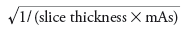
For conventional f iltered backprojection (FBP) images, the standard deviation in Hounsfield units (HU) due to Poisson noise [2] is proportional to:
This relationship applies when comparing corresponding regions in two images acquired with a different mAs or slice thickness. It also assumes that the underlying tissue has perfectly uniform HU. If the underlying tissue is heterogenous, then the standard deviation in HU equals:

where s1 is the standard deviation owing to the tissue texture, and s2 is the standard deviation owing to Poisson noise.
Poisson noise can be decreased by increasing the mAs. Modern scanners can perform tube current modulation, selectively increasing the dose when acquiring a projection with high attenuation. They also typically use bowtie filters, which provide a higher dose towards the center of the field of view compared with the periphery. There is a tradeoff between noise and resolution, so noise can also be reduced by increasing the slice thickness, using a softer reconstruction kernel (soft-tissue kernel instead of bone kernel) or blurring the image. Noise can also be reduced by moving the arms out of the scanned volume for an abdominal CT. If the arms cannot be moved out of the scanned volume, placing them on top of the abdomen should reduce noise relative to placing them at the sides. Similarly, large breasts should be constrained in the front of the thorax rather than on both sides in thoracic and cardiac CT. This is because the noise increases rapidly as the photon counts approach zero, which means that the maximum attenuation has a larger effect on the noise than the average attenuation.
In FBP, which is the standard reconstruction method on most scanners, the projection data are filtered to sharpen edges and the filtered data are then backprojected [1]. This assumes accurate projection data and ignores the fact that low photon counts result in a large Poisson error. On the other hand, iterative methods use a statistical model of the noise to improve the image on each iteration [3,4]. A wide range of techniques have been proposed, and all major vendors now offer various implementations of iterative reconstruction algorithms on their systems. The basic concept is to find the most probable image given: the projection data, the relationship between the image and the projection data (which can include Poisson noise, beam hardening and scatter), and the prior distribution of images (which often assumes that smoother images are more probable). This optimization problem is too difficult to solve analytically and is thus solved iteratively. With noisy projection data, there is a wide range of different images that are consistent with the measured projection data. The prior distribution of images directs the iterative reconstruction to pick a smoother image out of the range of possible images.
Iterative methods require faster computer chips, and have only recently become available for clinical use. One iterative method, model-based iterative reconstruction (MBIR; GE Healthcare, WI, USA) [5,6], received US FDA approval in September 2011 [101]. MBIR substantially reduces image noise and improves image quality, thus allowing scans to be acquired at lower radiation doses (Figure 3) [2]. Furthermore, owing to the tradeoff between noise and resolution, these methods will also probably be important for reducing noise in higher resolution images.

Figure 3: Iterative reconstruction reduces noise and improves image quality. (A) Filtered backprojection image obtained at low dose (50 mA) is extremely noisy. (B) Model-based iterative reconstruction of the same low-dose scan (50 mA) has dramatically reduced noise, revealing new soft-tissue details. In particular, note the nodular cirrhotic liver and the details in the right renal hilum. (C) A higher dose (754 mA) filtered backprojection image confirms the details in the model-based iterative reconstruction image. Modified with permission from [4].
Compared with conventional FBP, iterative reconstruction has a different relationship between noise and dose, and has a different noise texture. With FBP, as the dose is reduced, both the noise and image quality become worse. On the other hand, with MBIR, noise and image quality are decoupled: as the dose is reduced the noise increases only slightly, but resolution worsens and new artifacts may be introduced at very low dose levels [2]. Thus, traditional measures, such as the signal-to-noise ratio, are not applicable for MBIR and other iterative reconstruction methods. The noise texture depends on the parameters of the MBIR [6]. Specifically, MBIR attempts to generate a smooth image while preserving edges and has adjustable parameters to control the tradeoff between smoothness and edge preservation. Thus, the noise tends to coalesce into small clusters of pixels with uniform HUs, resulting in what has been described as a ‘plastic’ appearance.
Noise can also be reduced by combining information from multiple scans, such as multiple contrast phases [7,8]. This has important implications for whole-organ dynamic contrast-enhanced perfusion imaging, where radiation dose is currently one of the limiting factors. A low-noise scan is created by averaging scans performed at multiple time points. The temporal resolution is recovered by multiplying the average scan by a per pixel weighting factor, which is the blurred image at that time point, divided by the blurred average image.
Beam hardening & scatter
Beam hardening and scatter are different mechanisms that both produce dark streaks between two high attenuation objects, such as metal, bone, iodinated contrast or barium. They can also produce dark streaks along the long axis of a single high-attenuation object (Figures 4 & 5A) [1]. Bright streaks are seen adjacent to the dark streaks. These artifacts are a particular problem in the posterior cranial fossa and with metal implants (metal artifacts are discussed further in the ‘Metal artifact’ section below).

Figure 4: Beam hardening in simulated scans. (A–D) Simulated scans without and (E–H) with beam hardening, showing that dark streaks occur along the lines of greatest attenuation, and bright streaks occur in other directions. Scatter produces artifacts that look similar to this. Also note the subtle decrease in Hounsfield units just beneath the surface of the ‘abdomen’, which is caused by beam hardening. This is called cupping artifact and it is corrected by the simple beam hardening correction built in to modern scanners.

Figure 5: Metal Deletion Technique reduces many different types of metal artifacts, and can reveal new findings. (A) Dark streak between hip replacements is mostly due to beam hardening and scatter. (B) The Metal Deletion Technique image more clearly shows a fluid collection adjacent to the left hip replacement. (C) Sharp, thin alternating streaks surrounding an aneurysm coil are mostly due to motion and undersampling. (D) Metal Deletion Technique image reveals hemorrhage around the coil. (E) Smoothly undulating streaks around cholecystectomy clips are due to windmill artifact. (F) Metal Deletion Technique reduces this artifact.
Beam hardening is seen with polychromatic x-ray sources. As the x-ray passes through the body, low-energy x-ray photons are attenuated more easily and the remaining high-energy photons are not attenuated as easily. Thus, beam transmission does not follow the simple exponential decay seen with a monochromatic x-ray. This is a particular problem with high atomic number materials, such as bone, iodine or metal. Compared with low atomic number materials, such as water, these high atomic number materials have dramatically increased attenuation at lower energies (for low-energy x-rays, attenuation is primarily due to the photoelectric effect, and is proportional to Z3/E3, where Z is the atomic number and E is the energy. At high energies, attenuation is primarily due to Compton scatter and is proportional to 1/E).
Compton scatter causes x-ray photons to change direction (and energy) and thus end up in a different detector [9]. This creates the greatest error when the scattered photon ends up in a detector that otherwise would have very few photons. In particular, if a metal implant blocks all photons, then the corresponding detector element will only detect scattered photons. Scatter also becomes more significant with an increased number of detector rows because a larger volume of tissue is irradiated.
Thus, for highly attenuated x-ray beams, beam hardening and scatter both cause more photons to be detected than expected, resulting in dark streaks along the lines of greatest attenuation. In addition, the high pass filter used in FBP exaggerates differences between adjacent detector elements, producing bright streaks in other directions (Figure 4).
Scanning at a higher kV results in a harder x-ray beam and thus less beam-hardening artifacts. In addition, metal is more ‘transparent’ to higher energy photons, making it less likely to block all photons, thus reducing scatter artifacts. However, the tradeoff is that there is less tissue contrast at high kV.
Modern scanners perform a simple beamhardening correction that assumes an average amount of beam hardening, given the measured attenuation [10]. However, higher atomic number materials, such as metal, cause a higher than average amount of beam hardening and will thus not be fully corrected. This can be addressed using iterative reconstruction [11,12]. The first iteration is reconstructed using uncorrected projection data. Metal and bone are then detected using a HU cutoff, and these are forward projected to determine how much bone and metal are present in each detector measurement. This information is then used to perform a custom beam-hardening correction for each detector element.
Dual energy CT reduces beam-hardening effects by scanning at two different energies. This information can be used to derive virtual monochromatic images, which do not suffer from beam-hardening effects. However, the virtual monochromatic images produced by dual energy CT assume that the x-ray absorption spectrum has an idealized shape, without K-edges, which is clearly just an approximation [13]. In addition, dual energy CT does not correct for scatter, which is an important factor in many scans [9,14], especially if the metal blocks nearly all photons.
Most scanners use an antiscatter grid in front of the detector to reduce scatter. Scatter can also be estimated (using a scatter kernel, or from measurements made just outside the field of view), and then subtracted from the detector measurements. Finally, the image can be reconstructed iteratively, where the scatter correction is estimated using the image from the previous iteration [15,16]. However, in cases where metal blocks all photons (and thus all detected photons are due to scatter), soft-tissue information for those detector elements is lost and cannot be retrieved using scatter correction.
Pseudoenhancement
Pseudoenhancement of renal cysts refers to the fact that simple renal cysts have spuriously increased HUs after administration of intravenous contrast. This is caused by beam hardening and scatter, even though it does not have the streaks that are more classically associated with beam hardening. The same mechanism is responsible for the increased density seen just inside the skull on head CT.
Areas that are surrounded by a ring of highdensity material become brighter due to beam hardening and scatter (Figure 4D & H). One way to understand this phenomenon is by analogy to Figure 4C & G. Just inside the dark streaks formed by the three implants, there is a bright triangle. This is exactly analogous to the apparent high density seen inside a ring of high density.
Pseudoenhancement decreases with the distance from enhancing renal tissue. Thus, there is more pseudoenhancement in smaller cysts, and HU measurements should be performed as far away from the enhancing renal tissue as possible. In conventional CT, pseudoenhancement of up to 28 HU is seen [17]. This may be decreased with dual energy CT [18]. However, it is not eliminated, because dual energy CT only gives approximate mono-energetic images and does not correct for scatter (as discussed above).
Motion artifact
Motion (patient, cardiac, respiratory or bowel) causes blurring and double images, as well as long-range streaks (Figure 6). The streaks occur between high-contrast edges and the x-ray tube position when the motion occurs. Faster scanners reduce motion artifact because the patient has less time to move during the acquisition. This can be accomplished with faster gantry rotation or more x-ray sources [4]. More detector rows allow a greater volume to be imaged in a single gantry rotation, thus increasing the distance between step-off artifacts from motion on coronal or sagittal reformats. Rigid body motion artifacts (mainly a problem with head CT, as shown in Figure 6) can be reduced using special reconstruction techniques [19]. Respiratory motion in cone-beam CT with slow gantry rotation can be estimated and corrected, thus reducing artifacts [20].

Figure 6: Motion artifact in a head CT. (A) Motion causes blurring and double images, (B) as well as long range streaks.
With a very fast scanner, the heart can be scanned during diastole within a single heartbeat, significantly reducing cardiac motion, thus allowing evaluation of the coronary arteries [21]. Alternatively, with ECG gating, projection data are acquired over multiple cardiac cycles and then reconstructed from data acquired during specific phases of the cardiac cycle [4]. This can be used to make 3D movies of a beating heart. With current scanners, evaluation is suboptimal at higher heart rates and for images obtained during systole [22]. Temporal resolution in cardiac CT can be improved using new techniques that work with limited projection data [23].
Cone-beam (multidetector row) & windmill (helical) artifacts
Helical multidetector row CT has some additional artifacts that are not seen in single detector row step-and-shoot CT. On the other hand, the significantly reduced scan time reduces motion artifact.
In helical CT, the table is continuously advanced as the x-ray tube rotates around the patient. As the detector rows pass by the axial plane of interest, the reconstruction oscillates between taking measurements from a single detector row and interpolating between two detector rows. If there is a high-contrast edge between the two detector rows, then the interpolated value may not be accurate. This creates smooth periodic dark and light streaks originating from high-contrast edges, which are called windmill artifacts (Figure 5E). These are more prominent on thin slices and the vanes of the windmill rotate as one scrolls through axial slices. A similar mechanism is responsible for stair-step artifacts (serrations on coronal or sagittal reformats) [24] and zebra artifacts (periodic stripes of more or less noise at the image periphery seen on coronal or sagittal reformats); these are shown in Figure 7.

Figure 7: Zebra and stair-step artifacts. (A) Zebra artifacts (alternating high and low noise slices, arrows) due to helical interpolation. These are more prominent at the periphery of the field of view. (B) Stair-step artifacts (arrows) seen with helical and multidetector row CT. These are also more prominent near the periphery of the field of view. Therefore, it is important to place the object of interest near the center of the field of view.
In multidetector row CT, the projection planes (defined by the x-ray source and the detector row) are not exactly parallel to the axial plane (except for the center detector row). In the simplest 2D FBP reconstruction, the projection planes for each detector row are assigned to the closest axial plane based on where they intersect the center of rotation. If there is a high-contrast edge in the z-direction between the axial plane and the projection plane, this creates streaks, as well as stair-step artifacts (Figure 7). These effects are worse with an increased number of detector rows. These artifacts can be reduced with Adaptive Multiple Plane Reconstruction (AMPR), which uses tilted planes for reconstruction [25]. Cone-beam reconstructions, which reconstruct the entire 3D volume at the same time using the correct multidetector row geometry [26], also reduce this artifact, but are much slower. Clinical flat panel detector CT scanners use cone-beam reconstruction.
Metal artifact
Metal streak artifacts are extremely common, seen in 21% of scans in one series [27]. They are caused by multiple mechanisms, some of which are related to the metal itself and some of which are related to the metal edges. The metal itself causes beam hardening, scatter effects and Poisson noise, which are discussed above. Beam hardening and scatter result in dark streaks between metal with surrounding bright streaks (Figure 5A).
The metal edges cause streaks due to undersampling, motion, cone-beam and windmill artifacts [28]. The large discontinuities in detector measurements created by metal edges are amplified by the filter in FBP. In the limit of perfect data with infinite resolution, these edges cancel out away from metal. However, with undersampling or imperfections in the data (caused by motion, cone-beam or windmill effects), they do not exactly cancel, resulting in thin bright and dark streaks originating from the metal (Figure 5C & E).
Metal artifacts are particularly pronounced with high atomic number metals, such as iron or platinum, and less pronounced with low atomic number metals, such as titanium. In some cases (i.e., dental fillings on head CT scan), patient positioning or gantry tilt can angle the metal outside of the axial slices of interest.
Several techniques have been proposed for metal artifact reduction [27,29–31]. We developed an iterative method called the Metal Deletion Technique (MDT) [27], which is based on the principle that projection data involving or near metal is less accurate, owing to the mechanisms discussed above. MDT starts with raw projection data from the scanner and then only uses high quality non-metal data to reconstruct the non-metal portions of the image. Metal pixels are deleted from the reconstructed image and on each iteration, the inaccurate metal data are replaced with forward projected values from the previous iteration. This means that instead of trying to look through the metal to see soft tissue, we look around the metal. It also means that any features that can only be seen by looking through metal will be lost. In particular, structures within a few millimeters of metal are blurred out.
An initial evaluation of MDT showed that it had the best image quality when compared with FBP and two metal artifact reduction methods [27]. In two out of 11 scans, the improved image quality revealed important new findings. This includes a case of rectal cancer (in a patient with bilateral hip replacements) that was originally missed when only reviewing the images produced by the scanner.
Raw projection data from the scanner is stored in a proprietary format and, therefore, is not always accessible. Fortunately, the raw data can be estimated by forward projecting the reconstructed image. Using this technique, a follow-up study of 80 patients showed that MDT improved image quality 73% of the time for small metal implants and 75% of the time for large metal implants [32]. MDT had better image quality than all three other metal artifact reduction techniques tested.
At Stanford Hospital, we have integrated metal artifact reduction into our Picture Archiving and Communication System (PACS). The “Digital Imaging and Communications in Medicine (DICOM) send” function is used to send scans to a server that automatically reduces artifacts and sends the processed images back to PACS as a new series under the same accession. This procedure works with images from any scanner, and it does not require any manual drawing of regions of interest or tuning of parameters. We have found this to be particularly useful for radiation oncology [33], interventional radiology [34], orthopedics and neurosurgery applications (Figure 5).
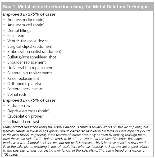
In some cases, MDT decreases resolution or introduces new artifacts. Thus, MDT images must be reviewed in conjunction with the original images produced by the scanner. Some portions of the image may be more clearly seen on the original image and other portions are more clearly seen on the MDT images. Our review of 102 cases shows the types of metal devices that tend to produce the best results (Box 1).
Out of field ‘artifact’
Despite popular belief [35,36], moving an object far outside the field of view does not necessarily create new artifacts. Existing artifacts (i.e., Poisson noise or metal artifacts) do not change with the field of view. The filter in FBP is extremely local, meaning that detector measurements far outside the field of view have minimal impact on pixels inside the field of view (Figure 8).

Figure 8: In filtered backprojection, the projection data are filtered to sharpen edges and the filtered data are then backprojected. The filter (shown above) is extremely local. For example, detector elements ±9 only have a weight of -0.5% relative to detector element 0. This means that detector measurements far outside the field of view have minimal impact on pixels inside the field of view.
Many modern scanners produce bright pixels at the edge of the field of view when the object being scanned extends outside the field of view. This is in fact due to a suboptimal implementation of FBP and can be fixed with a better reconstruction algorithm (Figure 9).

Figure 9: Filtered backprojection can reconstruct images acquired using a field of view smaller than the object being scanned. Top row shows the fields of view, second row shows sinograms, third row shows filtered sinograms and bottom row shows filtered backprojection reconstructions. A sinogram is a plot of the projection data (horizontal axis is the tube angle, and vertical axis is the detector number). (A) Full field of view. (B) Limited field of view, with the sinogram outside the field of view set to zero. This creates a sharp edge, which is amplified by the filter in filtered backprojection, creating a bright rim at the edge of the field of reconstruction. This appears to be what many modern CT scanners do. (C) Limited field of view, with the sinogram outside the field of view set to the end values in order to prevent discontinuities. This avoids the artifactual bright rim. There is still a small error at the edge of the field of view, which can be reduced using more sophisticated methods [44,45] or by scanning a slightly larger field of view.
Conclusion
Since its introduction in 1972, CT has seen several generations of improvements, including multidetector row helical CT, improved spatial and temporal resolution, dual energy CT, and iterative reconstruction. Many artifacts from the early days of CT are now substantially reduced, but some artifacts remain, and new technologies have introduced new, incompletely characterized artifacts.
Remarkable progress has been made in the past few years on iterative techniques for reducing metal artifacts and noise. These techniques not only improve image quality, but can also reduce the radiation dose, improve spatial resolution and improve diagnosis. However, with iterative reconstruction, noise and image quality are decoupled, which will require new measures of image quality as well as subjective evaluation. Iterative methods typically have adjustable parameters that control image smoothness, edge preservation and other features. The effect of these parameters on image quality and noise texture should be studied.
Dual energy CT reduces beam hardening but not scatter. Thus, some dark streaks between high-attenuation objects, as well as pseudoenhancement of renal cysts, remain in a dual energy scan.
Limited field of view CT (also known as interior CT) enables imaging of a small region of interest inside the body (i.e., the spine or tumors) at a lower dose.
Future perspective
Iterative reconstruction has been studied since the 1970s, but only recently have computer chips become fast enough for their routine clinical use. In commercial scanners, the reconstructions are typically performed using custom chips – application-specific integrated circuits or field-programmable gate arrays. Researchers tend to use the graphics processing unit or central processing unit in commodity hardware, which is slower than using custom chips, but much cheaper for small numbers of chips, and easier to reprogram [37]. Further improvements in computer power are likely to lead to improved iterative techniques. In particular, more accurate noise and artifact models, as well as conebeam reconstructions, will require additional calculations.
Further advances in CT hardware are also on the horizon. Inverse geometry CT is a new scanner geometry that uses a large array of multiple x-ray sources and smaller detector array [38,39], which eliminates cone-beam artifacts and potentially reduces scatter and radiation dose.
The highest resolution clinical scanners are flat panel detector (cone beam) scanners with a resolution of 75 μm (NewTom 5G). Scanners with a resolution in the micron range are also known as Micro-CT scanners. This resolution allows visualization of structures that are not seen on routine clinical CT (Figure 10). However, several issues need to be addressed before this resolution can actually be attained in routine clinical practice. First, high resolution increases noise, which may be acceptable for imaging high-contrast structures such as bone, but may obscure soft-tissue boundaries. This can be addressed using a higher dose or by using iterative reconstruction to reduce noise. Second, motion limits resolution, which can be addressed by motion correction techniques or with faster tube rotation speed. Laboratory and industrial CT scanners have a resolution as good as 50 nm (Xradia nanoXCT). Improved resolution enables visualization of individual cells on pathology specimens [40]. Interestingly, FBP (but not current iterative techniques) can reconstruct small fields of view using data from tightly collimated beams (Figure 9). This little-known fact could theoretically be used to obtain ultra-high resolution images of specific regions of interest inside the body (e.g., spine, tumors) at a lower dose. In addition, it could be used to obtain low-dose perfusion images of tumors.

Figure 10: Micro-CT reveals details of bony trabeculae. (A) Micro-CT of a dog
vertebra at 0.1 mm resolution. The scale bar is 1 cm. (B) The same scan
downsampled to 0.625 mm resolution, which is a typical resolution for clinical
multidetector row scanners.
Image (A) courtesy of Mark L Riccio from Cornell Imaging, Cornell University
(NY, USA).
Dual energy CT systems scan at two energy levels, which enables beam-hardening correction, and produces two HU numbers at each pixel, allowing for greater differentiation of different materials [41]. However, dual energy is not sufficient to capture the full absorption spectrum – for example, it does not detect K-edges that are unique to specific materials. By contrast, energy-sensitive photon-counting CT measures the full x-ray energy spectrum and thus can be used to detect K-edges [42], allowing accurate identification of specific materials, such as protein versus hemorrhage [43]. This should also result in improved reduction of j and scatter artifacts.
The main limitation of energy-sensitive photon counting CT is that since each photon must be detected individually, it can currently only be performed at low doses (20 mAs in one study). Iterative methods for noise reduction would be helpful in this application.
Although CT is a mature technology, there are many advances still on the horizon. We look forward to seeing what the future brings.
Acknowledgements
We thank S Hsieh, D Sze and L Shin for helpful comments on the manuscript. ML Riccio from Cornell Imaging provided the image in Figure 10.
Financial & competing interests disclosure
FE Boas has a patent pending on the Metal Deletion Technique (MDT) for metal artifact reduction. D Fleischmann has received research support from General Electric Healthcare and Siemens Medical Solutions. The authors have no other relevant affiliations or financial involvement with any organization or entity with a financial interest in or financial conflict with the subject matter or materials discussed in the manuscript apart from those disclosed.
No writing assistance was utilized in the production of this manuscript.
References
Papers of special note have been highlighted as:
• of interest
• • of considerable interest
- Hsieh J. Computed Tomography: Principles, Design, Artifacts, and Recent Advances. SPIE Press, Bellingham, WA, USA, 265–305 (2003).
- Fleischmann D, Boas FE, Tye GA, Sheahan D, Molvin LZ. Effect of low radiation dose on image noise and subjective image quality for analytic vs iterative image reconstruction in abdominal CT. Presented at: Radiological Society of North America. Chicago, IL, USA, 1 December 2011.
- Vandenberghe S, D’Asseler Y, van de Walle R et al. Iterative reconstruction algorithms in nuclear medicine. Comput. Med. Imaging Graph. 25(2), 105–111 (2001).
- Fleischmann D, Boas FE. Computed tomography – old ideas and new technology. Eur. Radiol. 21(3), 510–517 (2011).
- Yu Z, Thibault JB, Bouman CA, Sauer KD, Hsieh J. Fast model-based X-ray CT reconstruction using spatially nonhomogeneous ICD optimization. IEEE Trans. Image Process 20(1), 161–175 (2011).
- Thibault JB, Sauer KD, Bouman CA, Hsieh J. A three-dimensional statistical approach to improved image quality for multislice helical CT. Med. Phys. 34(11), 4526–4544 (2007). nn Provides a detailed description of the Model Based Iterative Reconstruction algorithm, which reduces image noise, improves resolution and reduces helical artifacts.
- Liu X, Primak AN, Krier JD, Yu L, Lerman LO, McCollough CH. Renal perfusion and hemodynamics. accurate in vivo determination at CT with a 10-fold decrease in radiation dose and HYPR noise reduction. Radiology 253, 98–105 (2009).
- Supanich M, Tao Y, Nett B et al. Radiation dose reduction in time-resolved CT angiography using highly constrained back projection reconstruction. Phys. Med. Biol. 54, 4575–4593 (2009).
- Joseph PM, Spital RD. The effects of scatter in x-ray computed tomography. Med. Phys. 9(4), 464–472 (1982).
- Herman GT. Correction for beam hardening in computed tomography. Phys. Med. Biol. 24(1), 81–106 (1979).
- Joseph PM, Spital RD. A method for correcting bone induced artifacts in computed tomography scanners. J. Comput. Assist. Tomogr. 2(1), 100–108 (1978).
- Hsieh J, Molthen RC, Dawson CA, Johnson RH. An iterative approach to the beam hardening correction in cone beam CT. Med. Phys. 27(1), 23–29 (2000).
- Alvarez RE, Macovski A. Energy-selective reconstructions in x-ray computerized tomography. Phys. Med. Biol. 21(5), 733–744 (1976).
- Akbarzadeh A, Ay MR, Ghadiri H, Sarkar S, Zaidi H. Measurement of scattered radiation in a volumetric 64-slice CT scanner using three experimental techniques. Phys. Med. Biol. 55(8), 2269–2280 (2010).
- Ruhrnschopf EP, Klingenbeck K. A general framework and review of scatter correction methods in x-ray cone-beam computerized tomography. Part 1: scatter compensation approaches. Med. Phys. 38(7), 4296–4311 (2011).
- Ruhrnschopf EP, Klingenbeck K. A general framework and review of scatter correction methods in cone beam CT. Part 2: scatter estimation approaches. Med. Phys. 38(9), 5186–5199 (2011).
- Birnbaum BA, Hindman N, Lee J, Babb JS. Renal cyst pseudoenhancement: influence of multidetector CT reconstruction algorithm and scanner type in phantom model. Radiology 244(3), 767–775 (2007).
- Müller J, Vrtiska T, Howe B et al. The impact of dual energy CT on pseudo enhancement of kidney lesions. Proc. SPIE 7622, 76223I (2010).
- Yu H, Wang G. Data consistency based rigid motion artifact reduction in fan-beam CT. IEEE Trans. Med. Imaging 26(2), 249–260 (2007).
- Rit S, Wolthaus JW, van Herk M, Sonke JJ. On-the-fly motion-compensated cone-beam CT using an a priori model of the respiratory motion. Med. Phys. 36(6), 2283–2296 (2009).
- Leschka S, Stolzmann P, Desbiolles L et al. Diagnostic accuracy of high-pitch dual-source CT for the assessment of coronary stenoses: first experience. Eur. Radiol. 19(12), 2896–2903 (2009).
- Mahabadi AA, Achenbach S, Burgstahler C et al. Safety, efficacy, and indications of beta-adrenergic receptor blockade to reduce heart rate prior to coronary CT angiography. Radiology 257(3), 614–623 (2010).
- Tang J, Hsieh J, Chen GH. Temporal resolution improvement in cardiac CT using PICCS (TRI-PICCS): performance studies. Med. Phys. 37(8), 4377–4388 (2010).
- Fleischmann D, Rubin GD, Paik DS et al. Stair-step artifacts with single versus multiple detector-row helical CT. Radiology 216(1), 185–196 (2000).
- Flohr TG, Schaller S, Stierstorfer K, Bruder H, Ohnesorge BM, Schoepf UJ. Multidetector row CT systems and imagereconstruction techniques. Radiology 235(3), 756–773 (2005).
- Feldkamp LA, David LC, Kress JW. Practical cone-beam algorithm. J. Opt. Soc. Am. A 1(6), 612–619. (1984).
- Boas FE, Fleischmann D. Evaluation of two iterative techniques for reducing metal artifacts in computed tomography. Radiology 259(3), 894–902 (2011).
- De Man B, Nuyts J, Dupont P, Marchal G, Suetens P. Metal streak artifacts in x-ray computed tomography: a simulation study. IEEE Trans. Nucl. Sci. 46(3), 691–696 (1999).
- Kalender WA, Hebel R, Ebersberger J. Reduction of CT artifacts caused by metallic implants. Radiology 164(2), 576–577 (1987).
- Prell D, Kyriakou Y, Kachelrie M, Kalender WA. Reducing metal artifacts in computed tomography caused by hip endoprostheses using a physics-based approach. Invest. Radiol. 45(11), 747–754 (2010).
- Bal M, Spies L. Metal artifact reduction in CT using tissue-class modeling and adaptive prefiltering. Med. Phys. 33(8), 2852–2859 (2006).
- Golden C, Mazin SR, Boas FE et al. A comparison of four algorithms for metal artifact reduction in CT imaging. Proc. SPIE 7961, 79612Y (2011).
- Abelson J, Murphy J, Wiegner E et al. Evaluation of a metal artifact reduction technique in tonsillar cancer delineation. Pract. Radiat. Oncol. 2(1), 27–34 (2012).
- Hong R, Dhanani RS, Louie JD, Sze DY. Intravascular ultrasound-guided mesocaval shunt creation in patients with portal or mesenteric venous occlusion. J. Vasc. Interv. Radiol. 23(1), 136–141 (2012).
- Barrett JF, Keat N. Artifacts in CT: recognition and avoidance. Radiographics 24(6), 1679–1691 (2004).
- Prokop M, Galanski M. Spiral and Multislice Computed Tomography of the Body. Prokop M, Galanski M, van Der Molen AJ, Schaefer- Prokop C (Eds). Thieme Medical Publishers, NY, USA, 220 (2003).
- Yan G, Tian J, Zhu S, Dai Y, Qin C. Fast cone-beam CT image reconstruction using GPU hardware. J. Xray Sci. Technol. 16, 225–234 (2008).
- Mazin SR, Star-Lack J, Bennett NR, Pelc NJ. Inverse-geometry volumetric CT system with multiple detector arrays for wide field-of-view imaging. Med. Phys. 34(6), 2133–2142 (2007).
- Schmidt TG, Star-Lack J, Bennett NR et al. A prototype table-top inverse-geometry volumetric CT system. Med. Phys. 33(6), 1867–1878 (2006).
- Watz H, Breithecker A, Rau WS, Kriete A. Micro-CT of the human lung: imaging alveoli and virtual endoscopy of an alveolar duct in a normal lung and in a lung with centrilobular emphysema – initial observations. Radiology 236, 1053–1058 (2005).
- Graser A, Johnson TR, Chandarana H, Macari M. Dual energy CT: preliminary observations and potential clinical applications in the abdomen. Eur. Radiol. 19(1), 13–23 (2009).
- Iwanczyk JS, Nygard E, Meirav O et al. Photon counting energy dispersive detector arrays for x-ray imaging. IEEE Trans. Nucl. Sci. 56(3), 535–542 (2009).
- Boll DT, Patil NA, Paulson EK et al. Focal cystic high-attenuation lesions: characterization in renal phantom by using photon-counting spectral CT – improved differentiation of lesion composition. Radiology 254(1), 270–276 (2010).
- Hsieh J, Chao E, Thibault J et al. A novel reconstruction algorithm to extend the CT scan field-of-view. Med. Phys. 31(9), 2385–2391 (2004).
- Yu H, Wang G. Compressed sensing based interior tomography. Phys. Med. Biol. 54(9), 2791–2805 (2009).
- General Electric Company. GE Healthcare unveils ultra-low dose CT technology with profound image clarity. www.genewscenter.com/content/detail.aspx?r eleaseid=13159&newsareaid=2 (Accessed 12 November 2011)
• • Introduces highly constrained backprojection for reducing noise in CT perfusion studies.
• • Introduces the Metal Deletion Technique for reducing metal artifacts, and shows that it improves image quality and may also affect the diagnosis.
• CT of human autopsy lungs at 14 μm resolution shows individual alveoli.
• • Shows the first clinical energy-sensitive photon-counting CT images, with an energy resolution of 9.8 keV.
■ Website