Perspective - Imaging in Medicine (2010) Volume 2, Issue 5
MRI of the prostate: potential role of robots
Jurgen J Fütterer†1, Sarthak Misra2 and Katarzyna J Macura31Department of Radiology& Interventional Radiology (667), Radboud University Nijmegen Medical Center, Geert Grooteplein 10, 6500 HB Nijmegen, The Netherlands
2Control Engineering Group, MIRA – Institute of Biomedical Technology & Technical Medicine, University of Twente, Enschede, The Netherlands
3The Russell H Morgan Department of Radiology & Radiological Science, The Johns Hopkins University, Baltimore, USA
- *Corresponding Author:
- Jurgen J Fütterer
Department of Radiology& Interventional Radiology (667)
Radboud University Nijmegen Medical Center
Geert Grooteplein 10, 6500 HB Nijmegen
The Netherlands
Tel: +31 243 614 545
Fax:+31 243 540 866
E-mail: j.futterer@rad.umcn.nl
Abstract
Prostate cancer is the most frequently diagnosed malignancy in the male population. Transrectal ultrasoundguided biopsy is still the imaging modality of choice in detecting prostate cancer. However, with prostate cancer being detected at an earlier stage, most prostate cancers tend to be isoechoic to the surrounding healthy prostatic tissue and, therefore invisible, resulting in transrectal ultrasound-guided biopsy having a positive predictive value of only 15.2%. MRI of the prostate has a superior soft-tissue contrast resolution, high spatial resolution and multiplanar capability. The ability to localize prostate cancer with MRI provides an opportunity to utilize magnetic resonance (MR) guidance for prostate biopsy. A number of MR‑compatible robots, ranging from a simple manipulator to a fully automated system, have been developed to biopsy suspicious prostate cancer areas. When combining MRI with fast imaging sequences, it is possible to track the needle or organ deformation in real time. As technology matures, precise image guidance for prostate interventions performed or assisted by specialized MR-compatible robotic devices may provide a uniquely accurate solution for guiding the intervention, directly based on MR findings and feedback. Such an instrument would become a valuable clinical tool for biopsies directly targeting imaged tumor foci and for delivering tumor-centered focal therapy.
Keywords
MRI; prostatic neoplasm; robotics
Every year, 220,000 new cases of prostate cancer are detected. Approximately 18% of these cases will be treated with brachytherapy [1,2]. Over 1.2 million prostate needle biopsies are carried out every year in the USA. Systematic transrectal ultrasound (TRUS)-guided biopsy is the most frequently used technique for detecting prostate cancer and is the most commonly used method for guiding brachytherapy. Several robotic systems have been proposed for TRUS-guided brachytherapy [3–7]. However, TRUS-guided biopsy has only a 32–43% detection rate [8,9], and needle deflection and seed misplacement may go unnoticed during the biopsy.
Presently, with prostate cancer being detected at an earlier stage, most prostate cancers tend to be isoechoic to the surrounding healthy prostatic tissue imaging. MRI provides more detailed anatomical images of the prostate compared with TRUS imaging [10]. Therefore, for the purpose of intervention in the prostate gland, diagnostic or therapeutic, MRI guidance offers the possibility of more precise targeting that may be crucial to the success of prostate interventions. However, access within the scanner is limited for manual instrument handling and the magnetic resonance (MR) environment is the most demanding among all imaging equipment with respect to the instrumentation used. A solution to this problem is the use of MR-compatible robots, specifically designed to operate within the constrained space and environmental restrictions of the MR scanner, enabling real-time interventions.
Building an MR-compatible robot is a very challenging engineering task, because, in addition to the material restrictions that MR instruments have, the robot requires actuators and sensors that have limited interference with the magnetic field of the MR scanner. Several important design problems must be overcome before a successful MR-compatible robot application can be built.
A number of MR-compatible robots, ranging from simple manipulators to a fully automated system, have been developed proposing various solutions to the design challenge. Several systems have already been tested clinically for prostate biopsy and brachytherapy. As technology matures, precise image guidance for prostate interventions performed or assisted by specialized MR-compatible robotic devices may provide a uniquely accurate solution for guiding the intervention directly based on MR findings and feedback. Such an instrument would become a valuable clinical tool for biopsies directly targeting imaged tumor foci and delivering tumor-centered focal therapy.
Design requirements of MR-compatible robots, MR-compatible materials, actuators, image-to-robot registration and MR-compatible prostate interventional systems will be discussed in this article.
Minimally invasive surgery
Manual minimally invasive surgery currently employed in clinical practice (e.g., tissue biopsy, brachytherapy and tissue ablation) usually involves the insertion of needles. The required targeting accuracy is application dependent, and needs to be greater when placing the needle in the brain or eye (micrometer range) than when placing it in the prostate or liver (millimeter range) [11]. Such procedures are generally performed under image guidance, using CT, MRI and ultrasound to visualize the target anatomy of the intervention, the surrounding tissue structures and any surgical instruments as they are moved proximal to the anatomical region of interest. In contrast to CT, MRI does not expose the patient to ionizing radiation, making it ideal for real-time image-guided interventions. When combining MRI with fast imaging sequences it is possible to track the needle or organ deformation in real time. In contrast to ultrasound images, MRI provides good soft-tissue contract.
During manual minimally invasive surgery, needles can deviate from their intended paths owing to needle-induced organ deformation, tissue inhomogeneity and anisotropy, anatomical obstructions, and numerous physiological processes (e.g., respiration, fluid flow and edema). Inaccurate needle placement may result in suboptimal outcomes. Such targeting errors can be alleviated by using a system that robotically guides needles to their intended targets.
To date, most robot-assisted needle insertion systems aim to increase targeting accuracy through careful alignment of a rigid needle prior to insertion into tissue [12–23]. Two strategies have been developed to facilitate flexible needle steering within tissue. One uses symmetrically tipped needles, but these require extensive steering from the base, thereby causing large tissue deformation [24–26]. The other uses asymmetrically tipped needles that, owing to bending forces at the tip, naturally deflect when interacting with tissue [27–29]. This phenomenon can be harnessed by robotically controlling the base to improve targeting accuracy. However, none of these systems can function within an MRI environment, as working in an MRI environment imposes restrictions when designing and building mechatronic systems to be used in close proximity to the scanner bore. MR scanners use magnetic fields of high density. Therefore, conventional actuators made of ferromagnetic materials cannot be used near the scanner. Furthermore, these actuators also use electromagnetic motors, which would interfere with the scanner’s magnetic field. Hence, a new class of actuation system, which can be used in close proximity to the MR scanner, is required. For maximal precision, a system is required that integrates preoperative plans, derived from needle– tissue interaction models and anatomical details, with intraoperative image-guided feedback for tracking and controlling the path of the needle.
Design requirements of MR‑compatible robots
Designing an MR-compatible robot for realtime guidance inside the MR scanner is recognized to be a complex task consisting of several steps and numerous demanding considerations:
• Selecting MR-compatible materials;
• Building MR-compatible actuators and position sensors;
• Designing a robot-to-image registration system that would allow precise guidance of the robot based on MR image feedback, and performing and tracking its development according to device regulations for clinical use and implementation of clinical trials.
Robots have stringent requirements for image compatibility, precision, sterility, safety, size and ergonomics. Among all types of imagers, the MR scanner is the most demanding and the development of MR robots is a very challenging engineering task. However, this also makes MR-compatible devices multi-imager compatible especially if radiolucent, artifact-free materials are used for the parts located in the immediate proximity of the imaging site [30].
MR- compatible materials
MR compatibility has been a tough hurdle of device developers, in particular, for robot developers who want to design MR-compatible systems [31]. Within the imager, ferromagnetic materials are exposed to very high magnetic interaction forces and heating may occur in conductive materials by electromagnetic induction. Whether metals can be used in an MR scanner depends on how they interact with the radio frequency and gradient fields. Carefully designed, short isolated structures with no loops can be used without distorting the radio frequency and gradient coils. The use of electricity may cause interference and lead to signal-to-noise attenuation, signal distortions and image artifacts. As such, most of the components commonly used in robotics may not be used in close proximity of the MR scanner. For example, the ubiquitous electromagnetic motor is clearly MR incompatible because its functions are based on magnetism.
Several nonferrous metals, such as titanium and nitinol, have been found to be acceptable for small-size parts and are being used in commercial MRI instrumentation. However, for noninterference with electromagnetism, the ideal materials should be nonmagnetic but also dielectric. These include plastics, ceramics, rubbers and glasses. From the energetic point of view, electricity is not MR compatible because currents generate electromagnetic waves and require conductors for wirings. Hydraulics could be a good choice but raise contamination concerns caused by leakage. On the other hand pnematics is an ideal choice, since it is decoupled from electromagnetism.
Actuators
Commercially available motors are not made of MR-compatible materials. The precision of motion, noninterference with the MR scanner and medical safety requirements cannot be met with such off-the-shelf actuators. As mentioned previously, pneumatic actuation is a fundamentally flawless option for MR compatibility [30]. A German research group, from Forschungszentrum Karlsruhe, were the first to realize this after multiple attempts with piezo actuation [32,33]. Their last version used a cylinder for driving an end-effector axis [34] and their report gives a well-reasoned presentation of these advantages.
In general, the major limitation of pneumatic actuators has been their reduced precision in controlled motion [35]. Pneumatics is traditionally used for free-spinning motion, such as drills (MR compatible [34]), or in industrial automation, such as opening and closing gates. Pneumatic motors (turbine or cylinder based) are fast and powerful, but notoriously hard to control for precise motion. Furthermore, MR-compatible pneumatic servo-controlled systems require long hoses for connection to the valves, which are placed outside the scanner room. The compressibility of the air in the hoses, coupled with the friction of the actuator and valves, makes the system highly nonlinear, hardly manageable, susceptible to small disturbances and raises significant safety concerns for use in medical applications. A system currently under development considers the use of piezoelectric valves, which would allow the valves to be placed closer to the scanner to shorten the hoses [36].
Piezoelectric motors have been used effectively in prostate devices [37,38] and have been demonstrated in other MR robot applications to have statistically insignificant effects on imaging with specially designed controller circuitry [32]. Rather than coping with the incompatibilities of piezoelectric motors, trying to manage the existing types of pneumatics, while avoiding known engineering problems, the Johns Hopkins Urology Robotics Laboratory chose to create a new type of motor, specifically for clinical applications. The PneuStep Motor was a breakthrough technology for MR compatibility [39].
The PneuStep motor is a pneumatic step motor. Directional motion in incremental steps is controlled by a signed digital input. Motion is controlled from a standard step-motion control card. A special electronic driver was designed to cyclically actuate three binary pneumatic valves based on the pulse and direction signals of the motion-control card. Three air hoses drive the new motor. Directional step motion is achieved by sequentially pressurizing the three ports, with pneumatic-commutation pressure waves. Internally, a new mechanism is used to convert the pneumatic waves in a stepped, high-precision, rotary motion. The basic motor is rotary, but the built-in gear-head transmission can be configured for either rotary or linear output of various step sizes. As for electric steppers, the motor could be controlled through an openloop mechanism. However, for medical safety, the motor was instrumented with sensors that measure the motion of the motor and can be used either for control feedback or as a redundant sensor. The sensors are optical and connected with fibers. An electro–optical interface connects the sensors back to the motion-control card, which transmits quadrature-encoded signals; this closes the feedback loop. The motor was also designed with a fail-safe operation as a hardware characteristic; in case of malfunction it may stall, but not unwind.
The PneuStep is entirely constructed of nonmagnetic and dielectric materials: plastics, ceramics, crystals and rubbers. It operates on air and laser light, and is electricity free. The motor operates precisely and without interfering with the MR scanner, even if located at the image isocenter of virtually any magnetic field imager. Four long hoses connect the motor to its control located in an adjacent room. Three of these carry air and the fourth caries optical fibers for control signals.
Image-to-robot registration
For any type of image guidance, registration is the most important component affecting the precision with which the instrument is guided to its desired target. Registration is the mapping of the image and instrument coordinate spaces. Several registration methods have been proposed, generally grouped into two categories: methods that use the gradient field of the MR equipment to determine the location of a sensor mounted on the instrument, typically called active marker methods, and more common methods that use fiducial markers placed on the instrument for observing it in the image and calculating the position of the instrument in the image space. Generally, gadolinium-doped water markers, which created clear signals on the MR image, are used as passive fiducials. Passive fiducials with specific geometry are placed on the instrument/robot and the MR image of the robot is taken. The image of the fiducial is recognized in a more or less automatic manner by an image-processing algorithm. Several registration methods have been proposed for obtaining the registration mapping based on imaged fiducials. Perhaps the most general technique is the imageto- model method, in which the known geometry of the fiducial (the model) is superimposed over the segmented geometry of the imaged fiducial (the image). The transformations (rotations and translations) applied to one of these geometries in the overlap process produce the mathematical estimation of the registration mapping, which is typically represented in the form of a 4 × 4 transformation matrix.
If a target is selected in the image, the registration software gives coordinates robot, which passed through the inverse-kinematics of the robot gives the position of the robot required to aim the robot to the target, and, vice versa, if the robot is reoriented the registration could tell what image point it targets. Registration is one of the most important factors in image-guided navigation.
In general, both the active marker and the fiducials are capable of providing good registration results. The main advantage of the active markers is that, in addition to the registration, these also provide continuous position measurements that are essential to the navigation process. With fiducial markers, the registration is performed typically once at the beginning of the procedure and, following navigation, is robotic or tracked with other methods. Despite these advantages, the active marker has limited applications because its structure and calibration is highly dependent on the MR scanner hardware, creating a serious obstacle for the interscanner portability of the device.
Ferromagnetic stainless steel needles cannot be used in MR-guided procedures owing to the field nonuniformities resulting from the large magnetic susceptibility differences between needle and tissue. Generally, gradient-echo sequences are more sensitive to spin dephasing, promoted by the local field inhomogeneities occurring around the needles, because gradient echo sequences lack a 180° refocusing pulse [40]. Spin echo or turbo spin echo will cause less image artifacts compared with the gradient-echo sequence. Furthermore, prostate motion and needle divergence are known causes of source displacement [41]. During needle insertion into the prostate, the prostate will be moved and this will cause deformation as a result of its elastic properties. An automatic tapping device was developed to overcome prostate movement and deformation [42].
MR- guided prostate interventions with special passive devices
A few studies have investigated direct MR-guided needle interventions despite the limited access within the scanner and the lack of remotely controlled instruments. Menard et al. performed several high-dose brachytherapy studies using a needle template guide registered to the MRI [43]. The study demonstrated both the feasibility and advantages of MR guidance, but also revealed the need for remote instrumentation, since numerous table moves were required to access the patient. Numerous transperineal biopsies and brachytherapy were performed in a 0.5-Tesla (T) open MR scanner [44]. Barnes et al. also reported a transperineal prostate biopsy in a patient with recurrent prostate cancer after brachytherapy and demonstrated that MR guidance was useful for targeting [45].
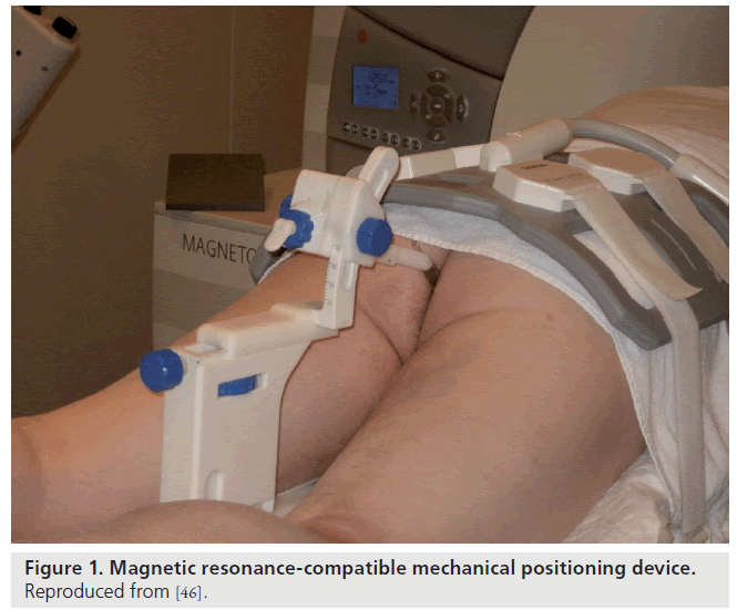
Beyersdorf et al. designed a MR-compatible mechanical positioning device that guides the needle during prostate core-needle biopsy; the needle guide is visible on both T1- and T2-weighted MR images (Figure 1) [46]. Using this device, biopsy was performed transrectally on 12 patients with elevated prostate-specific antigen levels. Engelhard et al. [47] and Anastadiadis et al. [48] used a similar and modified device to study patients with previous negative prostate biopsies. The detection rates ranges between 28 and 55.5% after one negative biopsy [48]. A 3-T multiparametric MRI approach consisting of T2-weighted MRI, diffusion-weighted imaging and dynamic contrast-enhanced MRI has a median MRI-guided biopsy time of just 35 min and can generate an average of four biopsy cores per patient [49].
Fightinger et al. used a comparable manual transrectal prostate biopsy system, for an open MR scanner [50]. The position of the entire device was calculated using microcoil antennas around the radioactive seeds. Unfortunately, these manual positioning systems require the patient to be withdrawn from the scanner to perform the biopsy or to adjust the needle placement.
At the NIH, transrectal MR-guided prostate biopsies and brachytherapy were performed in a closed-bore 1.5-T scanner [43,51]. A custom endorectal MR probe incorporating an imaging coil, special position tracking coils (active marker) and a needle guide was used [37,52,53]. Position tracking from the coils is used to calculate the desired orientation of a needle guide. Based on this information, the physician manually adjusts the device and inserts the needle. A recent report demonstrated improved cancer detection in MR-guided biopsies but only in patients for whom the repeat biopsies were not performed immediately following the TRUS [54,55]. One of the limitations of passive devices is dependence on manual operation.
MRI-compatible prostate interventional systems
There are various ways to include robot-assisted MRI-guided needle insertion systems into the diagnostic and therapeutic procedure. Unlike closed-bore MR scanners, the open MR imager enables the physician to have close patient access and almost real-time imaging. Unfortunately, the low image quality means that a combination with previously acquired closed-bore images is required [56]. In addition, there are several manually powered robot-assisted needle insertion systems. An extensive review of MRI-compatible systems is provided by Elhawary et al. [38]. Pondman et al. presented an overview of the MRI-compatible techniques in a systematic review [56].
DiMaio et al. developed an MR-compatible integrated system for planning and performing robotic transperineal intraprostatic needle insertion [57]. The hardware was based on the system developed by Chinzei and Miller [58] and experiments were performed on phantom tissue. Susil et al. described a transrectal system for needle placement for prostate interventions [52]. Four canine studies were presented and targeting accuracy of within 2 mm was achieved. Krieger et al. presented a three-degrees-of-freedom passive mechanical system, which accomplished incremental motion measurement using fiberoptical encoders and mechanical scales [59]. The compact design enabled the setup to be tested on different MR scanners and targeting accuracy of the system was evaluated in phantom prostate experiments.
MRI-compatible robots have previously used piezoelectric motors that are free of ferromagnetic parts. However, the high frequencies necessary to produce motion creates image distortion if operated within 0.5 m of the isocenter [34]. Consequently, the motors must be switched off during imaging procedures, thereby losing the advantages of real-time imaging during robot-assisted intervention.
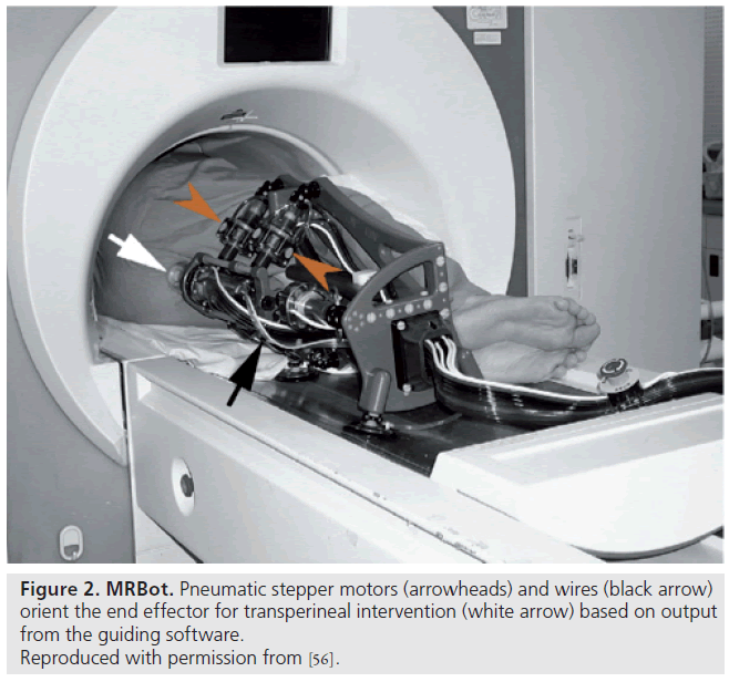
Unlike most previous work presented by Elhawary et al. [38], which used piezoelectric actuation, Stoianovici et al. were the first group of researchers to develop a pneumatically actuated MRI-compatible robot designed for transperineal interventions in the prostate (Figure 2) [60]. The robot, known as MRBot, has six degrees of freedom and can be configured for use in biopsy, thermal and radiofrequency ablation or brachytherapy [61]. The robot is controlled outside the MRI room. Preclinical testing on phantom, cadaver and animal experiments have been performed. Muntener et al. revealed promising outcomes of a mean seed-placement error of 0.72 ± 0.36 mm in phantom tissue [62,63].
Fischer et al. also developed a pneumatically controlled needle positioning device for prostate biopsies and brachytherapies [64]. Unlike the device developed by Stoianovici et al., the system by Fischer et al. did not require repositioning of the patient in the imaging space. The system proved the proof-of-concept of putting a controller in the scanner room. The controller consisted of wired optical encoders, short air hoses and piezo valves with adequate MR compatibility. Accuracy was high as 0.1 mm.
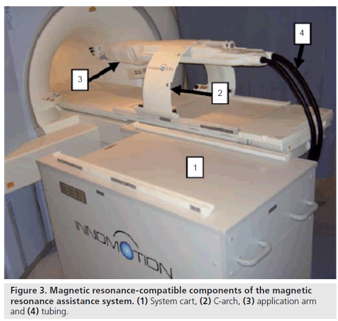
The German company Innomedic (Berlin, Germany) has developed a pneumatic robot for general CT- or MRI-guided needle procedures (Figure 3). This pneumatic robot is developed for transgluteal needle procedures. The robot attaches to the mobile table of the MR with an arch structure over the patient, presents five degrees of freedom and uses optical encoders, and image registration is performed by using passive fiducial markers. The robot is made for abdominal access, so it cannot be positioned in the scanner for prostate access. Zangos et al. evaluated a mean deviation of 0.35 mm of the needle tip in a gel phantom [65]. Although this uses pneumatic cylinders that are notoriously difficult to control and unsafe for clinical applications, the company developed an ingenious pneumatic cylinder to cope with these deficiencies, based on the idea of exploiting a high-sliding friction for a relatively low stiction. The Innomedic system is not approved by the US FDA, although it is approved for clinical use in Europe [36].
The University Medical Center (Utrecht, The Netherlands) robot, developed by van den Bosch et al., used a tapping motor for transperineal implantation of four gold markers in the prostate [66]. After manually pushing the needle into the patient’s skin, under MR image guidance, the robot tapped the needle into the desired position. This first patient study revealed an accuracy of over 1 mm. The high-speed tapping trajectory has been demonstrated to decrease tissue deformation during needle insertion [67,68].
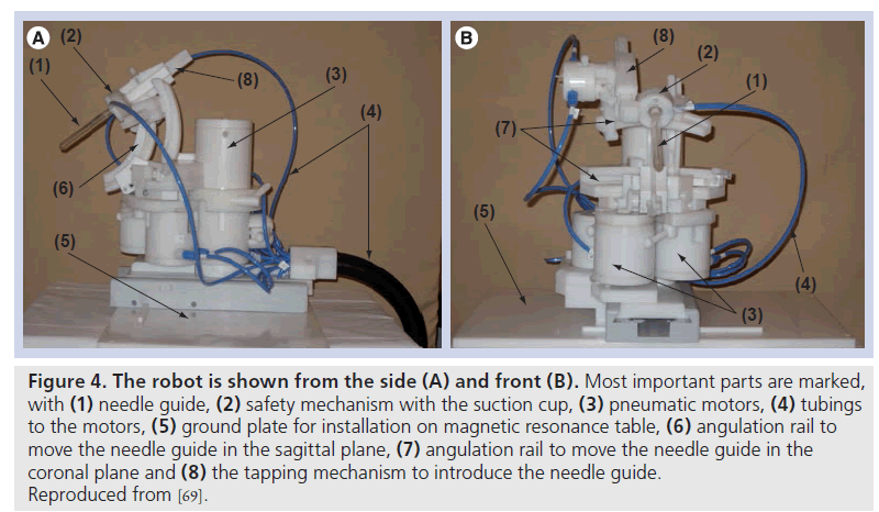
Figure 4. The robot is shown from the side (A) and front (B). Most important parts are marked, with (1) needle guide, (2) safety mechanism with the suction cup, (3) pneumatic motors, (4) tubings to the motors, (5) ground plate for installation on magnetic resonance table, (6) angulation rail to move the needle guide in the sagittal plane, (7) angulation rail to move the needle guide in the coronal plane and (8) the tapping mechanism to introduce the needle guide. Reproduced from [69].
The Radboud University Nijmegen Medical Centre (Nijmegen, The Netherlands) developed a MR-compatible transrectal prostate biopsy actuator (Figure 4). The system consists of the actuator and its controller unit. The controller unit includes a computer, motion control elements, and electro-pneumatic and electronic interfaces, which are located outside the MRI room. Plastic hoses are used to connect the actuator to the control unit. The actuator is constructed of nonmagnetic and dielectric materials to achieve MRI compatibility. The actuator uses pneumatic motors, pressured air used in these motors is generated in the controller unit and is transmitted through the plastic hoses. To meet standard safety requirements for use in medical applications, a safety mechanism, which consists of a vacuum sucking disk, was built in. When the force from the end effector applied on the patient is too high, the vacuum sucking disk will automatically release, thus, no force can be applied to the patient any longer. With five degrees of freedom, the needle guide can be manipulated in the desired position. The average in-plane error in a phantom study was 1.6 mm (range: 0.0–4.0 mm) [69].
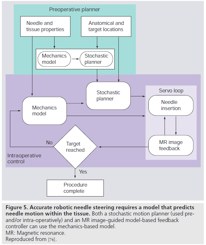
The MR-compatible devices provide precise control of needle insertion distance but, in order to ensure targeting accuracy, such devices must be integrated with preoperative planners and realtime MR-guided controllers. A system for steering flexible needles that incorporate planning and control has been developed to successfully drive a needle around obstacles to a desired target in phantom tissue [29]. The integrated system uses an image-guided feedback controller [70] from standard charge-coupled device cameras, and a stochastic motion planner [71] to track and control the needle path. These planners and controllers require a model of needle–tissue interaction. A general survey of surgical tool and tissue interaction models, which describes both physics- and nonphysics-based interaction models is provided by Misra et al. [72]. Misra et al., among others, provide a method to develop patientspecific models for interventions in the prostate [73]. In clinical practice, physically based parametric models of needle–tissue interactions are required for guiding needles within tissue [74]. Such interaction models coupled with planners and controllers need to be integrated with MRIcompatible hardware for accurate positioning of the needle within the prostate. Figure 5 depicts the use of mechanics-based needle–tissue interaction models, stochastic planners and MR-guided control systems to robotically steer needles to desired targets.
Figure 5. Accurate robotic needle steering requires a model that predicts needle motion within the tissue. Both a stochastic motion planner (used preand/ or intra-operatively) and an MR image-guided model-based feedback controller can use the mechanics-based model. MR: Magnetic resonance. Reproduced from [74].
Future perspective
The recent symbiosis between robotics and medical science has made rapid developments, particularly in imaging and interventions. The ultimate MR target of the robot for prostate biopsy purposes will most likely be provided by advanced multiparametric exams, such as MR spectroscopy, diffusion-weighted imaging and dynamic contrast-enhanced MRI. Robotics can also be used in studies investigating emerging treatment forms, such as focal therapy (i.e., laser therapy and cryosurgery), since it was designed to interact with a patient within any standard clinical closed-bore MR system. These treatment types could benefit greatly from the superior soft-tissue contrast and temperature mapping ability provided by MRI through intervention. However, before real-time MRI-guided focal therapy with the use of robotics can be realized and implemented, extensive research needs to be performed.
Acknowledgements
The authors would like to thank E Rozeboom for her helpful comments.
Financial & competing interests disclosure
This research is partially funded by the Dutch Ministry of Economic Affairs and the Province of Overijssel, within the Pieken in de Delta (PIDON) Initiative – Project MIRIAM. The authors have no other relevant affiliations or financial involvement with any organization or entity with a financial interest in or financial conflict with the subject matter or materials discussed in the manuscript apart from those disclosed.
No writing assistance was utilized in the production of this manuscript.
Bibliography
Papers of special note have been highlighted as:
* of interest
