Review Article - Imaging in Medicine (2010) Volume 2, Issue 4
MRI artifacts and correction strategies
Travis B Smith†1 & Krishna S Nayak11Ming Hsieh Department of Electrical Engineering, University of Southern California 3740 McClintock Avenue, EEB 412, Los Angeles, CA 90089, USA
- Corresponding Author:
- Travis B Smith
Ming Hsieh Department of Electrical Engineering
University of Southern California 3740 McClintock Avenue
EEB 412, Los Angeles, CA 90089, USA
Tel: +1 213 740 4652
Fax: +1 213 740 4651
E-mail: traviss@usc.edu
Abstract
Artifacts appear in MRI for a variety of reasons. Potential sources of artifacts include nonideal hardware characteristics, intrinsic tissue properties and biological behavior, assumptions underlying the data acquisition and image reconstruction process, and poor choice of scanning parameters. Careful study design and scanning protocols can prevent certain artifacts from occurring, but some are unavoidable. Numerous correction methods have been developed to mitigate the corruptive effects of artifacts and improve image diagnostic quality. These methods include special pulse sequence designs, improved scanning procedures and equipment, and advanced postprocessing algorithms. Recognizing artifacts and understanding their underlying causes are important when interpreting images and choosing a correction approach.
Keywords
artifact correction ▪ artifacts ▪ magnetic resonance imaging ▪ motion ▪ MRI ▪ off-resonance
During the 35 years since the first nuclear MRI scanners were made, MRI has become a powerful and widely used clinical imaging modality. MRI is frequently utilized in neurological, musculoskeletal and cardiovascular examinations owing to the excellent soft-tissue contrast and spatial resolution of its images. Owing to its unique sensitivity to a range of physiological and biological parameters such as flow, chemical composition and molecular configuration, MRI is also well-suited for functional and metabolic studies. There is an enormous flexibility when selecting imaging parameters; tissue contrast, image resolution and anatomical coverage can all be optimized for each specific application. Both 2D and 3D images can be formed with no restrictions on the orientation of the imaging volume. Perhaps most importantly, because it does not rely on ionizing radiation, MRI is safe for serial examinations, dynamic (timeresolved) imaging studies and screening in asymptomatic subjects.
The MRI signal is created by a combination of a strong magnetic field (called the B0 field) typically generated by a superconductive coil, one or more radiofrequency (RF) fields, and several weak magnetic fields generated by three gradient coils. When a patient enters the scanner, the magnetic moments of protons within the body tend to align with the B0 field. An RF pulse tuned to the nuclear magnetic resonance (NMR) frequency (which is determined by the strength of the B0 field and the gyromagnetic ratio of the particular nuclei – typically hydrogen – being imaged) is transmitted, forcing the moments to oscillate at their resonant frequency [1]. This oscillation is detected by one or more receiver coils, demodulated and stored. Spatial encoding along three axes is performed by the gradient coils, which alter the magnetic field strength so that the resonance frequency varies linearly with position, permitting a Fourier-based interpretation of the space–frequency relationship [2]. During the scan, the spatial frequency content, or k-space, of the imaging volume is sampled according to a chosen k-space trajectory, image field-of-view and resolution. To fully sample k-space, multiple data acquisitions are often required, each covering a segment of the spatial frequency support. Once the desired k-space data have been acquired, spatial decoding and image reconstruction are performed, typically by an inverse Fourier transform (FT) [3]. The echo time, which is the interval between the RF pulse and a data acquisition, and the repetition time (TR), which is the interval between sequential data acquisitions, are two important scan parameters that influence image contrast, signal-to-noise ratio (SNR) and other image features.
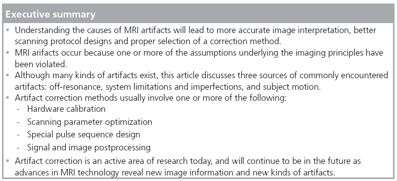
As with any other imaging modality, MRI is vulnerable to artifacts. These arise because one or more of the assumptions upon which the imaging principles depend have been violated. Often, several different kinds of artifacts occur simultaneously in an image. While some artifacts can be avoided by using proper scanning technique, even well-designed protocols implemented with well-maintained and calibrated systems cannot stave off artifacts. Consequently, many correction procedures have been developed to minimize or eliminate artifacts. Methods of artifact correction typically involve one or more of the following strategies: hardware improvement, scan parameter and pulse sequence optimization, and postprocessing. This article discusses various artifact correction methods for three common types of artifacts. Identifying artifacts and understanding their causes are important for designing robust scanning protocols, pulse sequence designs and data processing algorithms.
What is an artifact?
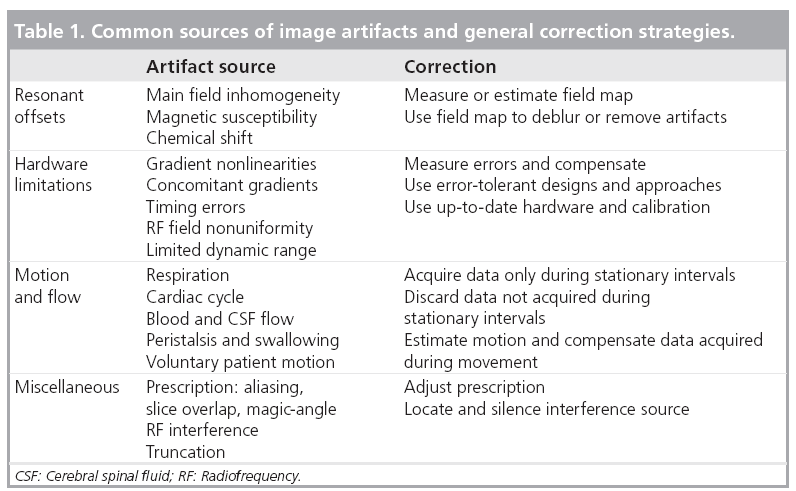
There is no standard definition of an artifact in MRI. This is partly owing to the wide variety of artifacts that can occur and partly because, in some situations, the same artifact can be a nuisance to one application and a boon to another. For instance, the variations in the magnetizability, or susceptibility, of certain materials lead to displacement, blurring and signal dropout artifacts; yet the susceptibility difference induced by the oxygenation of hemoglobin is the foundation of the blood oxygen level dependent signal in functional MRI studies [4]. Phase contrast techniques are another example: the additional signal phase terms generated by blood flow can cause image artifacts, but also provide an opportunity for phase-sensitive velocity measurements [5]. For this article, we will notionally define an artifact as any image content that does not correspond to the distribution of the object being scanned or to random noise. Common sources of image artifacts are: inherent properties of the patient or object being scanned, motion and other data inconsistencies, and scanning system and hardware imperfections. Table 1 lists several artifacts along with general approaches for correction. In the following sections, several kinds of MRI artifacts will be described along with various correction techniques.
Resonance offsets
Offsets in the NMR frequencies that are not compensated during image reconstruction will produce image artifacts. Any phenomenon that disturbs the linear relationship between frequency and spatial position will violate the assumptions of the Fourier reconstruction, induce phase errors in the signal and generate artifacts. These so-called ‘off-resonance’ artifacts are generally attributable to unwanted magnetic field variations inside the imaging volume. Inhomogeneity of the main B0 field, magnetic susceptibility [6] and chemical shift are typical sources of resonant frequency offsets. The B0 field is never perfectly uniform throughout the bore of the magnet. This inhomogeneity causes additional, spatially-smooth frequency modulation. Appropriate high-order shimming and prescan calibration can adjust the gradient waveforms to compensate for this [7]. Differences in magnetic susceptibility, which typically occur along air-tissue interfaces, near surgical implants or clips, or around metallic bodies or molecules such as deoxyhemoglobin, will also alter the resonant frequency. Artifacts caused by chemical shift occur in some molecules such as lipids because the protons in the nuclei are magnetically shielded by their surrounding electrons, experience a different effective magnetic field, and therefore oscillate at a shifted resonant frequency.
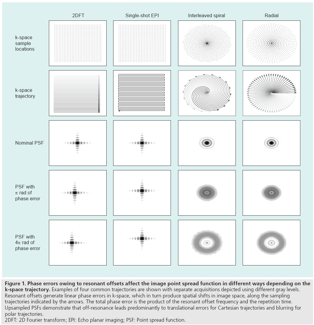
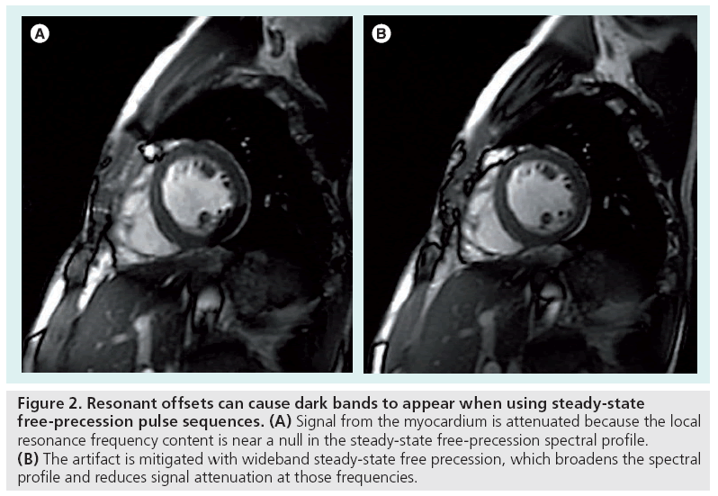
The appearance of an artifact caused by a resonant offset depends on the k-space trajectory and the pulse sequence used during the scan. The effect of an uncompensated frequency shift can be visualized by examining the image point spread function, which reveals the distortion or blurring kernel induced by the shift. Figure 1 depicts example point spread functions for common k-space trajectories with various amounts of resonant offset phase error. Spin warp (2DFT) trajectories traverse k-space on a regular or Cartesian grid using a sequence of parallel lines (phase encode lines) [8], and resonant offsets therefore cause only simple spatial translations. The lack of off-resonance blurring in spin warp sequences makes them a popular choice for many clinical and research applications. Spiral [9] and radial (also called projection reconstruction or PR) [10] trajectories, which are more time-efficient and often used for rapid imaging, are vulnerable to blurring by off-resonance [11]. The blurring can be alleviated by reducing the duration of each spiral interleaf or radial spoke when possible. With an echo planar imaging (EPI) trajectory [12,13], another rapid sampling scheme in which the entirety of k-space is acquired after a single RF pulse, off-resonance causes spatial shifting and distortion owing to the low bandwidth along one direction. Off-resonance can also lead to banding artifacts with steadystate free-precession (SSFP) sequences [14], as shown in Figure 2. SSFP creates periodic nulls in the signal spectrum that attenuate any tissues resonating at frequencies near multiples of 1/TR. These artifacts can be mitigated by shimming or reducing the TR [7]. Alternatively, the SSFP spectral profile can be adjusted using dynamic phase cycling [15] or pulse sequence modifications such as wideband SSFP [16,17].
Figure 1: Phase errors owing to resonant offsets affect the image point spread function in different ways depending on the
k-space trajectory. Examples of four common trajectories are shown with separate acquisitions depicted using different gray levels.
Resonant offsets generate linear phase errors in k-space, which in turn produce spatial shifts in image space, along the sampling
trajectories indicated by the arrows. The total phase error is the product of the resonant offset frequency and the repetition time.
Upsampled PSFs demonstrate that off-resonance leads predominantly to translational errors for Cartesian trajectories and blurring for
polar trajectories.
2DFT: 2D Fourier transform; EPI: Echo planar imaging; PSF: Point spread function.
Figure 2: Resonant offsets can cause dark bands to appear when using steady-state free-precession pulse sequences. (A) Signal from the myocardium is attenuated because the local resonance frequency content is near a null in the steady-state free-precession spectral profile. (B) The artifact is mitigated with wideband steady-state free precession, which broadens the spectral profile and reduces signal attenuation at those frequencies.
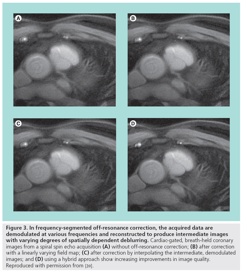
Blurring artifacts can be corrected with image postprocessing using phase-rewinding techniques. These techniques assume the offresonance behavior varies slowly with spatial position. If the acquired data are demodulated by a frequency offset and the image is reformed, then in the new image the blurring will be reduced in tissues resonating at or near that frequency offset. This process is approximately equivalent to changing the carrier frequency used in the quadrature receiver. If instead the data are reconstructed multiple times to form a set of intermediate images, each demodulated by different carrier frequency within the resonance offset bandwidth, then off-resonant tissues will be deblurred in at least one of the intermediate images. A composite image consisting of only the deblurred regions from each intermediate image can then be formed [18,19]. Selecting the appropriate regions from each intermediate image is guided by a field map, which shows the spatial distribution of the resonant offsets and is created from two (typically low-resolution) images, each acquired with a different echo time. The field map is often smoothed or constrained by fitting to low-order functions [20]. The intermediate images can also be mathematically combined together to improve accuracy or reduce the computational complexity [21]. Another deblurring technique cancels the phase imparted by the resonant offsets by numerically simulating the MR imaging process using the blurred image and the additive inverse of the field map to create a new data set, which is then reconstructed [22]. Figure 3 illustrates the potential improvement in image quality using off-resonance correction.
Figure 3: In frequency-segmented off-resonance correction, the acquired data are demodulated at various frequencies and reconstructed to produce intermediate images with varying degrees of spatially dependent deblurring. Cardiac-gated, breath-held coronary images from a spiral spin echo acquisition (A) without off-resonance correction; (B) after correction with a linearly varying field map; (C) after correction by interpolating the intermediate, demodulated images; and (D) using a hybrid approach show increasing improvements in image quality. Reproduced with permission from [20].
Correction methods have been developed to estimate the field map from the blurred image itself and eliminate the extra scan time required to acquire a field map. Instead of selecting deblurred regions in the intermediate images based on a field map, a local metric of the pixel energy in each intermediate image is used to estimate the off-resonance frequencies [11,23]. Variations of this method impose constraints on the estimated field map to improve robustness [24].
System limitations & imperfections
Practical limitations, imperfections and nonidealities in the hardware of an MRI scanner can also generate image artifacts. The gradientinduced magnetic fields, RF pulses and receiver hardware have physical constraints that can interfere with the assumptions underpinning MR image formation. Maxwell’s equations, for example, prohibit the creation of purely linear magnetic fields [25]. A practical consequence of this is that the gradient coils produce fields with nonlinear components called concomitant gradients, which cause spatially varying phase errors and signal loss similar to off-resonance artifacts. Since these errors are independent of echo time, they do not appear in the measured field map and instead must be corrected with reconstructions using an estimated field map [26,27]. Furthermore, the gradients are only (approximately) linear over a limited region, outside of which significant geometric warping can occur. The rapid cycling of the gradient fields during data acquisition leads to additional field distortions from eddy currents in the scanner conducting material, which naturally form to oppose changes in the magnetic field. Although modern scanners precompensate the gradient waveforms to mitigate this behavior, eddy currents can still be problematic in scans with high-amplitude, switched-field gradients. k-space trajectory deviations due to these gradient distortions lead to image warping and distortion artifacts. Such artifacts can be corrected by measuring the actual k-space sample locations and using these during image reconstruction instead of the nominal or assumed locations [28–30].
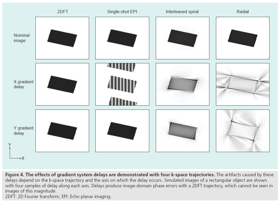
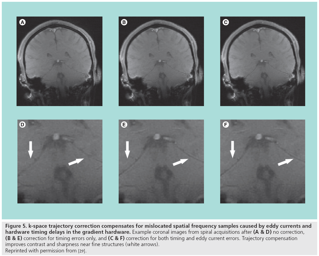
Hardware timing errors can also generate image artifacts. Delays in the order of tens of microseconds may exist between the three gradient coils, the RF transmitter and the receiver. Delays between the RF transmitter and the gradients will degrade the RF pulse performance and slice selection. Synchronization problems between the receiver acquisition hardware and the gradients, and timing errors among the gradients themselves, will perturb the k-space trajectory and produce artifacts during reconstruction, as shown in Figure 4. These delays can be compensated with accurate calibration and adjustment of k-space sample locations during reconstruction [29]. Results from one correction technique, which compensates for both gradient delays and the eddy current distortions without requiring new trajectory measurements for each scan, are shown in Figure 5.
Figure 4: The effects of gradient system delays are demonstrated with four k-space trajectories. The artifacts caused by these
delays depend on the k-space trajectory and the axis on which the delay occurs. Simulated images of a rectangular object are shown
with four samples of delay along each axis. Delays produce image-domain phase errors with a 2DFT trajectory, which cannot be seen in
images of this magnitude.
2DFT: 2D Fourier transform; EPI: Echo planar imaging.
Figure 5: k-space trajectory correction compensates for mislocated spatial frequency samples caused by eddy currents and
hardware timing delays in the gradient hardware. Example coronal images from spiral acquisitions after (A & D) no correction, (B & E) correction for timing errors only, and (C & F) correction for both timing and eddy current errors. Trajectory compensation
improves contrast and sharpness near fine structures (white arrows).
Reprinted with permission from [29].
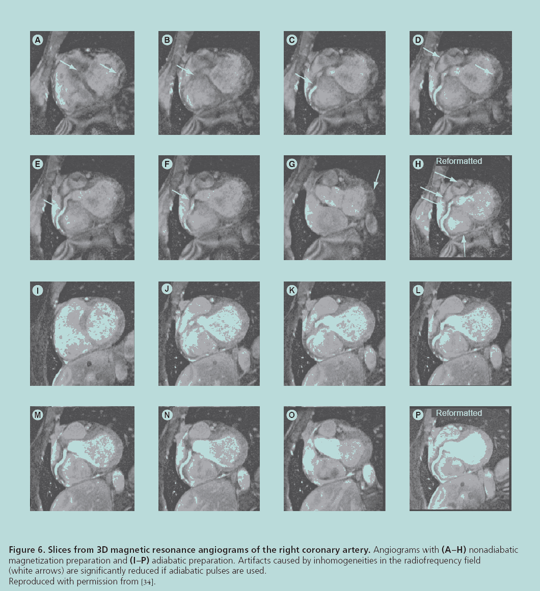
Another fundamental hardware limitation is the nonuniformity of the RF field, which should be considered when using surface coils or when the RF wavelength is similar to the size of the patient [31]. When the strength of the transmitted RF pulse varies with position, the signal power will be spatially modulated across the imaging volume. As a result, the reconstructed images will have shading artifacts, variable contrast and lower SNR. These artifacts can be corrected using RF pulses that do not depend on field homogeneity, such as adiabatic pulses [32–34], or by directly compensating for the nonuniformity when designing the pulse [35]. Angiography results demonstrating the improvement in image quality using adiabatic pulses are shown in Figure 6. Nonuniformity in the receive field also results in image shading because the receiver’s signal sensitivity varies across the patient. Surface coil intensity correction, which normalizes the image with a very low-resolution version of itself, can compensate for this. Other correction methods for image shading employ more sophisticated techniques such as regional histogram equalization [36] and information minimization [37].
Figure 6: Slices from 3D magnetic resonance angiograms of the right coronary artery. Angiograms with (A–H) nonadiabatic
magnetization preparation and (I–P) adiabatic preparation. Artifacts caused by inhomogeneities in the radiofrequency field
(white arrows) are significantly reduced if adiabatic pulses are used.
Reproduced with permission from [34].
Motion & flow
Standard image reconstruction assumes the patient, object or sample is perfectly stationary during the entire data collection time. Owing to voluntary or involuntary patient movement and motion caused by physiological processes, this rarely occurs. Many different kinds of motion can corrupt the images. Motion may be random – such as with patient movement, peristalsis, swallowing and eye movement – or periodic, as with the normal activities of the cardiac and respiratory cycles, and the pulsatility of vascular flow and cerebrospinal fluid.
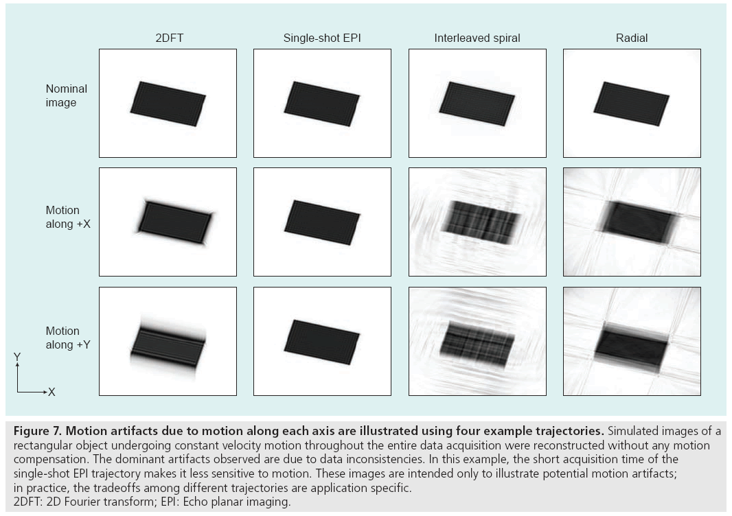
Motion degrades image quality in two ways, depending on when it occurs in the scan. If the motion takes place during a data acquisition interval (e.g., a phase encode line in 2DFT, an interleaf in spiral imaging, a spoke in radial imaging or the single shot in EPI), additional phase terms related to the motion path will be created in the data. On the other hand, motion between acquisition intervals causes inconsistencies because the data acquired before and after the movement do not correspond to the same anatomical arrangement or pose. The frequency content of each pose is therefore incompletely sampled and the image, which consists of a superposition of each undersampled pose, suffers from aliasing and displacement artifacts [38]. The aliasing artifacts manifest as ‘ghosting’ in 2DFT and EPI trajectories, and ‘streaking’ or ‘swirling’ in radial and spiral trajectories. In both cases, the decreased coherency of the acquired signals produces blurring, loss of resolution and lower image SNR, as shown in Figure 7.
Figure 7: Motion artifacts due to motion along each axis are illustrated using four example trajectories. Simulated images of a
rectangular object undergoing constant velocity motion throughout the entire data acquisition were reconstructed without any motion
compensation. The dominant artifacts observed are due to data inconsistencies. In this example, the short acquisition time of the
single-shot EPI trajectory makes it less sensitive to motion. These images are intended only to illustrate potential motion artifacts;
in practice, the tradeoffs among different trajectories are application specific.
2DFT: 2D Fourier transform; EPI: Echo planar imaging.
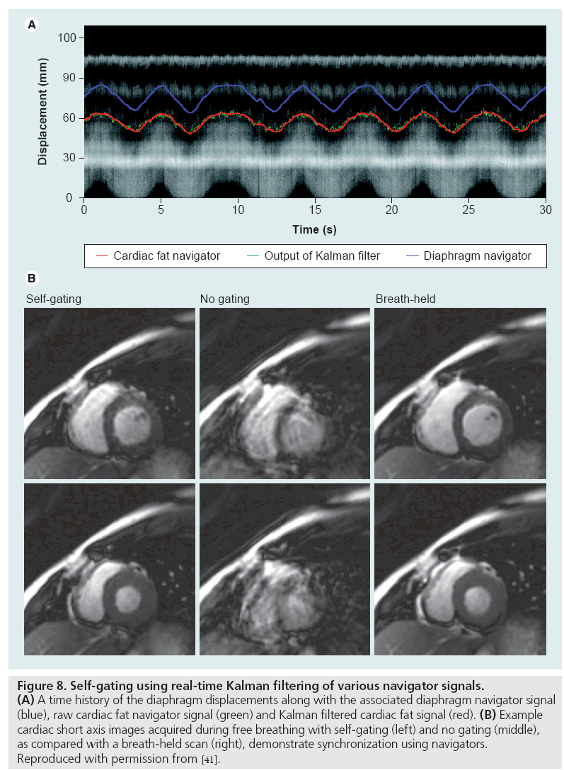
Data inconsistency artifacts can be mitigated using a combination of gating, navigators, motion correcting or motion-insensitive pulse sequence designs and postprocessing techniques. External gating methods use devices such as plethysmographs or electrocardiographic leads to synchronize data acquisition with cardiac phase or respiratory bellows to isolate intervals of minimal chest movement. Self-gating methods employ the MRI scanner itself to monitor movement with frequent, brief navigator scans between the data acquisition intervals. These navigators produce 1D images of the air-diaphragm interface (for respiratory motion compensation) or similar anatomical biomarker to prospectively or retrospectively synchronize the data acquisition [39–41]. Example results using a real-time navigator-based acquisition are shown in Figure 8. In addition to identifying quiescent intervals, the navigator signals can also be utilized during postprocessing to compensate for motion since they contain information about the motion-induced phase errors [42,43]. An important consideration when using navigator-based techniques is the accompanying increase in scan time or data volume. Recently, external optical motion tracking devices have been incorporated into scanning protocols to retrospectively or prospectively compensate for subject motion [44].
Figure 8: Self-gating using real-time Kalman filtering of various navigator signals. (A) A time history of the diaphragm displacements along with the associated diaphragm navigator signal (blue), raw cardiac fat navigator signal (green) and Kalman filtered cardiac fat signal (red). (B) Example cardiac short axis images acquired during free breathing with self-gating (left) and no gating (middle), as compared with a breath-held scan (right), demonstrate synchronization using navigators. Reproduced with permission from [41].
Vulnerability to motion artifacts can be alleviated by using motion-insensitive gradient waveforms, saturation pulses and fast scanning protocols. Artifacts caused by constant velocity motion can be mitigated with gradient moment nulling, wherein the first moments of the imaging gradients are zeroed at the echo time to cancel the phase accrual due to movement [45,46]. This approach is suitable for gradient echo sequences and can be adapted to reduce sensitivity to acceleration and higher-order motion. Spatial presaturation pulses can diminish flow artifacts by attenuating signals upstream of the imaging volume, thereby reducing the intensity of fluids flowing into the field of view [45]. Motion artifacts can also be minimized with single-shot sequences such as EPI, or by using other rapid scanning sequences such as SSFP with a short TR.
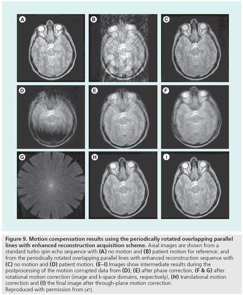
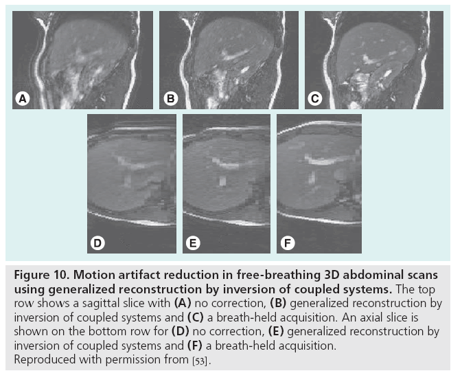
Motion-related data inconsistencies can be corrected using special pulse sequences and postprocessing. By repeatedly acquiring the central portion of k-space with short acquisitions, low spatial resolution information is obtained, which can guide postprocessing correction algorithms. This information is useful for correcting rigid-body translation and rotation [47,48], or more generally any affine transformation [49], of the anatomy that may occur during the scan by enforcing consistency constraints among the duplicate k-space samples. Figure 9 demonstrates the variety in the types of motion correctable by periodically rotated overlapping parallel lines with enhanced reconstruction. Alternatively, for standard pulse sequences, an entropy minimization criterion has been shown to compensate for bulk motion in standard pulse sequences [50]. Image-domain correction can also be performed using template tracking and low-order, piecewise motion models [51]. The generalized reconstruction by inversion of coupled systems approach, in which the image and motion model are jointly estimated using a priori information provided by simple sensors such as respiratory bellows, has been used to reduce artifacts from nonrigid movement in free-breathing acquisitions, as shown in Figure 10 [52,53].
Figure 9: Motion compensation results using the periodically rotated overlapping parallel lines with enhanced reconstruction acquisition scheme. Axial images are shown from a standard turbo spin echo sequence with (A) no motion and (B) patient motion for reference; and from the periodically rotated overlapping parallel lines with enhanced reconstruction sequence with (C) no motion and (D) patient motion. (E–I) Images show intermediate results during the postprocessing of the motion corrupted data from (D); (E) after phase correction, (F & G) after rotational motion correction (image and k-space domains, respectively), (H) translational motion correction and (I) the final image after through-plane motion correction. Reproduced with permission from [47].
Figure 10: Motion artifact reduction in free-breathing 3D abdominal scans
using generalized reconstruction by inversion of coupled systems. The top
row shows a sagittal slice with (A) no correction, (B) generalized reconstruction by
inversion of coupled systems and (C) a breath-held acquisition. An axial slice is
shown on the bottom row for (D) no correction, (E) generalized reconstruction by
inversion of coupled systems and (F) a breath-held acquisition.
Reproduced with permission from [53].
Conclusion
Artifacts are inevitable in medical imaging. Recognizing them is essential for image interpretation and selection of an appropriate artifact correction method. The best way to remove some artifacts is to avoid them altogether by using up-to-date, well-calibrated scanning hardware; accurate, per-patient prescans and shimming; and appropriate pulse sequences, gradient waveforms, and gating for the application of interest. When artifacts are unavoidable, artifact-insensitive or artifact-correcting pulse sequence designs, image-processing algorithms, and scan protocols should be employed.
Future perspective
New trends in MRI such as ultra-fast imaging, high-field scanners, SSFP, dynamic imaging and sparsity-based acceleration are introducing new kinds of artifacts, indicating that artifact correction will remain an active area of research in MRI. Commercial systems are therefore likely to incorporate more sophisticated and potentially automated calibration procedures and image postprocessing algorithms that avoid and correct, respectively, for the most significant classes of image artifacts in routine clinical applications. With time, the study of image artifacts will also lead to more accurate signal models and improvements in quantitative MRI.
Financial & competing interests disclosure
The authors receive grant support from GE Healthcare. The authors have no other relevant affiliations or financial involvement with any organization or entity with a financial interest in or financial conflict with the subject matter or materials discussed in the manuscript apart from those disclosed.
No writing assistance was utilized in the production of this manuscript.
References
Papers of special note have been highlighted as:
• of interest
• • of considerable interest
- Freeman R: A Handbook of Nuclear Magnetic Resonance. Longman Publishing Group, Essex, UK (1997).
- Bernstein MA, King KF, Zhou XJ: Handbook of MRI Pulse Sequences. Elsevier Academic Press, Burlington, MA, USA (2004).
- Twieg DB: The k-trajectory formulation of the NRM imaging process with applications in analysis and synthesis of imaging methods. Med. Phys. 10(5), 610–612 (1983).
- Brown GG, Perthen JE, Liu TT, Buxton RB: A primer on functional magnetic resonance imaging. Neuropsychol. Rev. 17(2), 107–125 (2007).
- Firmin DN, Nayler GL, Kilner PJ, Longmore DB: The application of phase shifts in NMR for flow measurement. Magn. Reson. Med. 14(2), 230–241 (1990).
- Schenk JF: The role of magnetic susceptibility in magnetic resonance imaging: MRI magnetic compatibility of the first and second kinds. Med. Phys. 23(6), 815–850 (1996).
- Schar M, Kozerke S, Fischer SE, Boesiger P: Cardiac SSFP imaging at 3 Tesla. Magn. Reson. Med. 51(4), 799–806 (2004).
- Edelstein WA, Hutchinson JMS, Johnson G, Redpath T: Spin warp NMR imaging and applications to human whole-body imaging. Phys. Med. Biol. 25(4), 751–756 (1980).
- Ahn CB, Kim JH, Cho ZH: High-speed spiral-scan echo planar NMR imaging. IEEE Trans. Med. Imag. 5(1), 2–7 (1986).
- Glover GH, Pauly JM: Projection reconstruction techniques for reduction of motion effects in MRI. Magn. Reson. Med. 28(2), 275–289 (1992).
- Noll DC, Pauly JM, Meyer CH, Nishimura DG, Macovski A: Deblurring for non-2D Fourier transform magnetic resonance imaging. Magn. Reson. Med. 25(2), 319–333 (1992).
- Mansfield P: Multi-planar image formation using NMR spin echoes. J. Phys. C. Solid State Phys. 10(3), L55–L58 (1977).
- Twieg DB: Acquisition and accuracy in rapid NMR imaging methods. Magn. Reson. Med. 2(5), 437–452 (1985).
- Carr HY: Steady-state free precession in nuclear magnetic resonance. Phys. Rev. 112, 1693–1701 (1958).
- Nayak KS, Hargreaves BA, Hu BS, Nishimura DG, Pauly JM, Meyer CH: Spiral balanced SSFP cardiac imaging. Magn. Reson. Med. 53(6), 1468–1473 (2005).
- Nayak KS, Lee HL, Hargreaves BA, Hu BS: Wideband SSFP: alternating repetition time balanced steady-state free precession with increased band spacing. Magn. Reson. Med. 58(5), 931–938 (2007).
- Lee HL, Shankaranarayanan A, Pohost GM, Nayak KS: Improved 3 Tesla cardiac cine imaging using wideband SSFP. Magn. Reson. Med. 63(6), 1716–1722 (2010).
- Noll DC, Meyer CH, Pauly JM, Nishimura DG, Macovski A: A homogeneity correction method for magnetic resonance imaging with time-varying gradients. IEEE Trans. Med. Imag. 10(4), 629–637 (1991).
- Schomberg H: Off-resonance correction of MR images. IEEE Trans. Med. Imag., 18(6), 481–495 (1995).
- Chen W, Meyer CH: Semiautomatic off-resonance correction in spiral imaging. Magn. Reson. Med. 59(5), 1212–1219 (2008).
- Man LC, Pauly JM, Macovski A: Multifrequency interpolation for fast off-resonance correction. Magn. Reson. Med. 37(5), 785–792 (1997).
- Kadah YM, Hu X: Simulated phase evolution rewinding (SPHERE): a technique for reducing B0 inhomogeneity. Magn. Reson. Med. 38(4), 615–627 (1997).
- Man LC, Pauly JM, Macovski A: Improved automatic off-resonance correction without a field map in spiral imaging. Magn. Reson. Med. 37(6), 906–913 (1997).
- Chen W, Meyer CH: Fast automatic linear off-resonance correction method for spiral imaging. Magn. Reson. Med. 56(2), 457–462 (2006).
- Kong JA: Electromagnetic Wave Theory. EMW Publishing, Cambridge, MA, USA (2005).
- Bernstein MA, Zhou XJ, Polzin JA et al.: Concomitant gradient terms in phase contrast MR: analysis and correction. Magn. Reson. Med. 39(2), 300–308 (1998).
- King KF, Ganin A, Zhou XJ, Bernstein MA: Concomitant gradient field effects in spiral scans. Magn. Reson. Med. 41(1), 103–112 (1999).
- Zhang Y, Hetherington HP, Stokely EM, Mason GF, Twieg DB: A novel k-space trajectory measurement technique. Magn. Reson. Med. 39(6), 999–1004 (1998).
- Tan H, Meyer CH: Estimation of k-space trajectories in spiral MRI. Magn. Reson. Med. 61(6), 1396–1404 (2009).
- Barmet C, De Zanche N, Wilm BJ, Pruessmann KP: A transmit/receive system for magnetic field monitoring of in vivo MRI. Magn. Reson. Med. 62(1), 269–276 (2009).
- Singerman RW, Denison TJ, Wen H, Balaban RS: Simulation of B1 field distribution and intrinsic signal-to-noise in cardiac MRI as a function of static magnetic field. J. Magn. Reson. 125(1), 72–83 (1997).
- Silver MS, Joseph RI, Hoult DI: Highly selective II/2 and II pulse generation. J. Magn. Reson. 59, 347–351 (1984).
- Garwood M, Ke Yong: Symmetric pulses to induce arbitrary flip angles with compensation for RF inhomogeneity and resonance offsets. J. Magn. Reson. 94(3), 511–525 (1991).
- Nezafat R, Stuber M, Ouwerkerk R, Gharib AM, Desai MY, Pettigrew RI: B1-insensitive T2 preparation for improved coronary magnetic resonance angiography at 3T. Magn. Reson. Med. 55(4), 858–864 (2006).
- Sung K, Nayak KS: B1+ compensation in 3T cardiac imaging using short 2D RF pulses. Magn. Reson. Med. 59(3), 441–446 (2008).
- DeCarli C, Murphy DGM: Local histogram correction of MRI spatially dependent image pixel intensity nonuniformity. J. Magn. Reson. Imag. 6(3), 519–528 (1996).
- Likar B, Viergever M, Pernus F: Retrospective correction of MR intensity inhomogeneity by information minimization. IEEE Trans. Med. Imag. 20(12), 1398–1410 (2001).
- Xiang QS, Henkelman RM: K-space description for MR imaging of dynamic objects. Magn. Reson. Med. 29(3), 422–428 (1993).
- Danias DG, McConnell MV, Khasgiwala VC, Chuang ML, Edelman RR, Manning WJ: Prospective navigator correction of image position for coronary MR angiography. Radiol. 203(3), 733–736 (1997).
- Nijm GM, Sahakian AV, Swiryn S, Carr JC, Sheehan JJ, Larson AC: Comparison of self-gated cine MRI retrospective cardiac synchronization algorithms. J. Magn. Reson. Imag. 28(3), 767–772 (2008).
- Spincemaille P, Nguyen TD, Prince MR, Wang Y: Kalman filtering for real-time navigator processing. Magn. Reson. Med. 60(1), 158–168 (2008).
- Ordidge RJ, Helpern JA, Qing ZX, Knight RA, Nagesh V: Correction of motional artifacts in diffusion-weighted MR images using navigator echoes. Magn. Reson. Imag. 12(3), 455–460 (1994).
- Anderson AW, Gore JC: Analysis and correction of motion artifacts in diffusion weighted imaging. Magn. Reson. Med. 32(3), 379–387 (1994).
- Dold C, Zaitsev M, Speck O, Firle EA, Hennig J, Georgios S: Advantages of limitations of prospective head motion compensation for MRI using an optical motion tracking device. Acad. Radiol. 13(9), 1093–1103 (2006).
- Ehman EL, Felmlee JP: Flow artifact reduction in MRI: a review of the roles of gradient moment nulling and spatial presaturation. Magn. Reson. Med. 14(2), 293–307 (1990).
- Haacke EM, Lenz GW: Improving MR image quality in the presence of motion by using rephasing gradients. AJR Am. J. Roentgenol. 148(6), 1251–1258 (1987).
- Pipe JG: Motion correction with PROPELLER MRI: application to head motion and free-breathing cardiac imaging. Magn. Reson. Med. 42(5), 963–969 (1999).
- Deng J, Omary RA, Larson AC: Multishot diffusion-weighted SPLICE PROPELLER MRI of the abdomen. Magn. Reson. Med. 59(5), 947–953 (2008).
- Manke D, Nehrke K, Bornert P: Novel prospective respiratory motion correction approach for free-breathing coronary MR angiography using a patient-adapted affine motion model. Magn. Reson. Med. 50(1), 122–131 (2003).
- Atkinson D, Hill DLG, Stoyle PNR et al.: Automatic compensation of motion artifacts in MRI. Magn. Reson. Med. 41(1), 163–170 (1999).
- Sussman MS, Stainsby JA, Robert N, Merchant N, Weight GA: Variable-density adaptive imaging for high-resolution coronary artery MRI. Magn. Reson. Med. 48(5), 753–764 (2002).
- Batchelor PG, Atkinson D, Irarrazaval P, Hill DLG, Hajnal J, Larkman D: Matrix description of general motion correction applied to multishot images. Magn. Reson. Med. 54(5), 1273–1280 (2005).
- Odille F, Vuissoz PA, Marie PY, Felblinger J: Generalized reconstruction by inversion of coupled systems (GRICS) applied to free-breathing MRI. Magn. Reson. Med. 60(1), 146–157 (2008).
• • Covers a very broad array of MRI topics with technical details and clinical examples.
• Provides a detailed explanation of magnetic susceptibility and its implications.
• Thorough summary and performance analysis of several important off-resonance correction methods.
• Simple and robust method for k-space trajectory measurement.
• Introduces new formalism for analyzing spatiotemporal data acquisitions.
• • Motion correction technique with significant clinical impact.
