Research Article - Imaging in Medicine (2016) Volume 8, Issue 2
The study of valve hybrid fractal stent for the next generation brain aneurysm treatment
Akihiko Ichikawa*1, Takahiro ITO2, Kouhei Shimogaito2, Takashi Kubo1 and Toshio Fukuda1,3,41Japan Society of Mechanical Engineering, Department of Mechatronics engineering, Meijo University, Japan
2Department of Mechanical Engineering, Meijo University, Japan
3Institute for Advanced Research, Nagoya University, Japan
4School of Mechatronic Engineering, Beijing Institute of Technology, Japan
- Corresponding Author:
- Akihiko Ichikawa
Japan Society of Mechanical Engineering
Department of Mechatronics engineering
Meijo University, Japan
Tel: +81-52-838-2604
E-mail: ichikawa- kihiko@nifty.com
Abstract
We propose a novel flow-diverter stent, “valve hybrid fractal stent” to treat the cerebral aneurysm what is one of a cerebrovascular disease. The stent has a valve part to path through a coil. The valve has fractal-pattern structures. So, the blood speed flowing into cerebral aneurysm is reduced. We had experiment of Particle Image Velocimetry (PIV) for evaluation of the inflow of cerebral aneurysm. By the experiment result, we visualized the stream line by using the cerebral aneurysm model. We succeeded in a speed reduction of the inflow with our valve hybrid fractal stent.
Keywords
Flow-diverter stent, fractal, hybrid fractal stent, MEMS, Particle Image Velocimetry (PIV)
Introduction
In this study, we focused on novel therapeutic device for the brain aneurysm. The worst cause of death is heart vessel disease and second one is cerebrovascular disease. The typical symptoms of vascular disease are vascular occlusion and aneurysm. In the previous study, clipping of the aneurysm is used as the treatment of the brain aneurysm. However, the skull of the patient is cut so we need a lot of time for hospitalization and cure. So, the minimally invasive medical method was developed using catheter, stent and coil. The catheter is inserted from the blood vessel of the thigh, and the coil or stent is moved into the brain aneurysm through the catheter [1-5]. These methods are succeeded in reduce of the burden of the patient but these method had problem of blood clot or flowing out of the coil. So, the flow-diverter stent was developed to solve these problems.
The flow-diverter stent has fine mesh patterns at the surface to obtain a flow diverter effect. The flow diverter effect is that controlling the flow in any direction. It is possible to suppress the inflow of the blood into the brain aneurysm [6-10]. However, this method also has a problem of blood flow control. Therefore, new medical devices to the brain aneurysm are needed.
Our research group developed a novel hybrid fractal stent to solve these problems [11-15]. We aim combination of stent treatment and coil treatment. The hybrid fractal stent has holes to through the coil and fractal pattern at the surface to get the fractal effect. However, the hybrid fractal stent has a problem. The hybrid fractal stent has a hole for insertion of catheter and coil. If the size of the brain aneurysm neck is smaller rather than the hole, the fractal effect is not activate enough.
We propose a valve hybrid fractal stent as the new device of endovascular treatment. The stent has valve mechanism and the surface of the valve is fabricated the fractal pattern. It can be cover the hole for coiling. This paper shows the design of the valve hybrid fractal stent, experimental result and evaluation.
Valve hybrid fractal stent
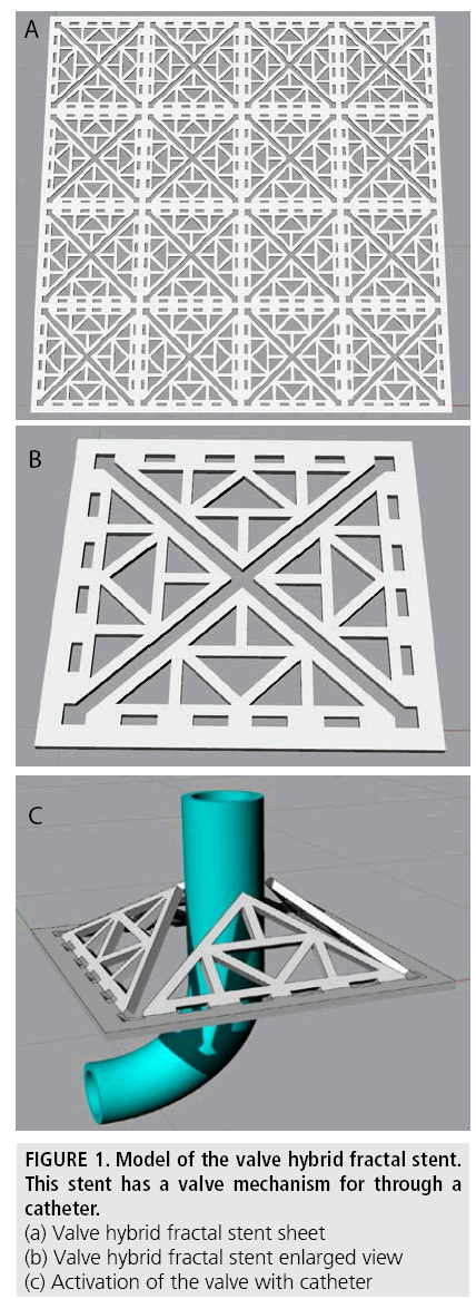
We propose the valve hybrid fractal stent is a stent which is fabricated the valve into the hole for the insertion of a catheter for the coil treatment. A catheter push the valve to open it, and the coil is inserted into the brain aneurysm. Thus, it is possible to prevent the inflow of blood from the hole of catheter.
FIGURE 1 shows the model of the valve hybrid fractal stent. FIGURE 1 (a) shows the sheet of the valve hybrid fractal stent. By using the fractal structure, the intravascular cells can grow and cover easier through the fractal pattern. It is assist the stent is buried in the early to vascular endothelial cells. FIGURE 1(b) and 1(c) show the part of the valve and Activation of the valve with catheter.
PIV experiment of the valve hybrid fractal stent
■Design of the valve hybrid fractal stent
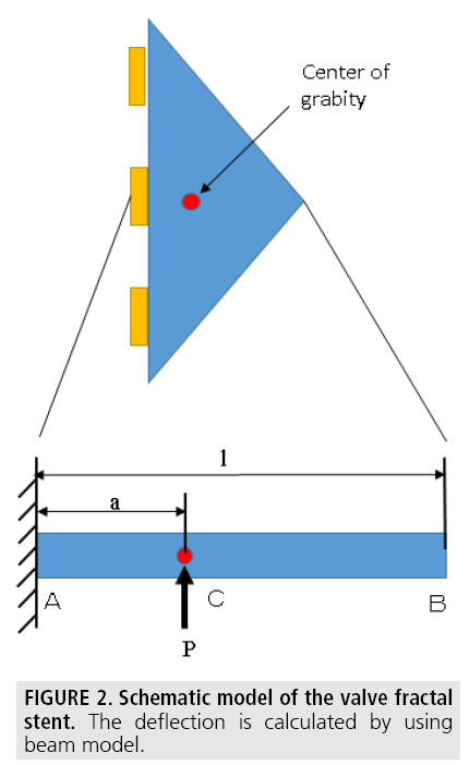
FIGURE 2 shows a schematic model of the valve fractal stent. In this study, to observe the effect of fluid suppression of the valve hybrid fractal stent, we use sheet of the stent. The stent sheet is made by wet etching method, the thickness is 0.05 [mm], and made by stainless plate (SUS310). Normally, stent is made by laser processing machine, but the processing accuracy is not enough for this valve hybrid fractal stent. And we use stainless plate because the nickeltitanium is difficult of wet etching.
Figure 2: Schematic model of the valve fractal stent. The deflection is calculated by using beam model.
We designed the hinge mechanism of the valve to prevent the blood flow. FIGURE 3 shows the model of the hinge mechanism. We analyze it as the beam structure. Here, l is length of the beam, a is distance from edge to the center of gravity, P is load of the center of the gravity, θ is deflection angle, y is deflection, E is young’s modulus and I is second moment of area.
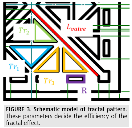
Figure 3: Schematic model of fractal pattern. These parameters decide the efficiency of the fractal effect.
The moment of the point C is M= P·a
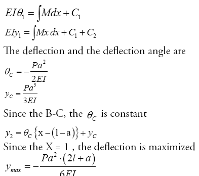
The pressure in the vessel it is assumed that 100 [mmHG],
100[mmHG]=133.32×10³ [Pa]=133.32×10² [N/m2]
This pressure is loaded to the valve, the pressure of loaded to the center of gravity P is
S =1.69×10⁻⁶ (m2 )
P = 133.32×102×1.69×10-6=0.023 [N]
While the thickness of the beam is 50 [μm], the second moment of area of the beam is
I=1.875×10⁻⁵
Young’s modulus is 3500 [Kg/mm2].
The maximum deflection of the beam is

This result shows that the beam can prevent the blood flow.
Then, we design the fractal patter. FIGURE 3 shows the model of the fractal pattern. Dr. Nagata, et. al. [16] calculated that the distance of the flow diverter effect is related with the fractal pattern and the after the flow interaction length scale [17-21].
Therefore, the after the flow interaction length scale is
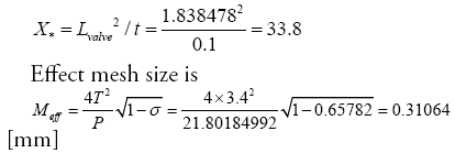
The distance from the fractal pattern is X
[mm],  is the border of the flow
diverter effect.
Here, X = 0.045X* = 0.045×33.8 =1.521[mm]. So the flow diverter effect is activated over 1.521[m]. The size of the aneurysm is about 8 [mm], so the flow diverter effect is activated in the brain aneurysm.
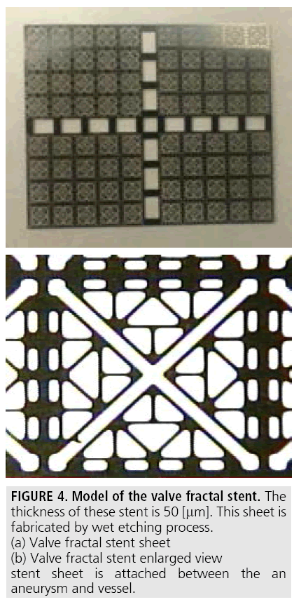
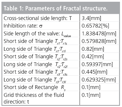
FIGURE 4 shows the fractal stent sheet. This sheet is made by wet etching process of MEMS. It is made of stainless plate which the sickness is 0.05 [mm] (TABLE 1).
Model of aneurysm
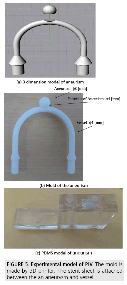
To observe the flow of the inside of the brain aneurysm model, we need a transparent model. We use transparent polymer, Poly- (dimethylsiloxane) (PDMS), for the base of the model. We use PDMS (DOW CORNING TORAY SILPOT 184 W/C, Toray co.) and ABS mold of the brain aneurysm which is made by 3D printer. To smooth the surface of the ABS model, we use acetone. The processed mold is soaked in the non-cured PDMS, then the PDMS is cured by heater. The ABS mold is solved by the acetone, we can made the transparent aneurysm model. FIGURE 5 shows the computer model of the aneurysm. The size of the radius is φ 8[mm] and the size of the neck is 4 [mm].
Figure 5: Experimental model of PIV. The mold is made by 3D printer. The stent sheet is attached between the an aneurysm and vessel.
We use 3D printer (UP Plus, OPT Technologies Co., Ltd.) which the accuracy is 0.15 [mm]. FIGURE 6 (b) shows the ABS mold of the brain aneurysm. We cut this model at the neck of the aneurysm, and both models are soaked in the non-cure PDMS. Then the PDMS with mold is heated at 80 degree for two hours for curing. After cure the PDMS, the mold are dissolved by acetone. Between the aneurysm neck and blood vessel, the stent sheet is put on and the PDMS molds are pressed by metal jig to prevent the leaking of the liquid.
PIV experiment
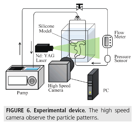
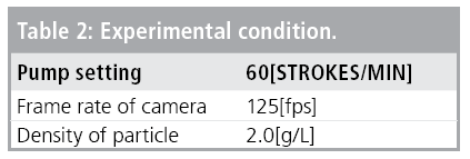
We use particle and pulsatile pump for PIV experiment. A laser beam is irradiated to the model to detect the particles, and the movie is recorded by the high-speed camera. The movie is analyzed by the PIV software. FIGURE 7 shows the experimental set-up. We use pulsatile pump (Harvard apparatus pulsatile blood pump 1405-048, Harvard Appartus CO., LTD.) to flow the liquid mixed with pure water and polystyrene beads the radius is φ 4[μm] for flow visualization. We use fiber laser (YML-5- 1064, IPG CO., LTD.), and record the movie by using high-speed camera (Photron 1DP, Photron CO., LTD.). (TABLE 2) shows the parameters of the experiment.
Experimental result
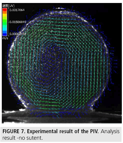
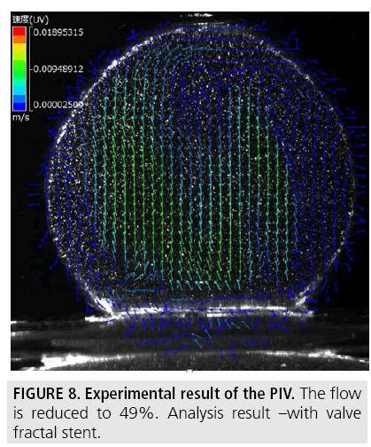
We perform the PIV experiment using the mold and the stent sheet, and non-stent model for the control. We use the experimental system as shown in FIGURE 7, and the movie of the experimental results are analyzed by using PIV software (DETECT. DipMotion2D). FIGURE 8 shows the result of the analysis. The maximum speed of the non-stent flow is 31 [mm/s] and the maximum speed with stent is 19 [mm/s]. So we succeeded in 49% reduction of the blood flow using our stent sheet. The flow pattern of non-stent is that the flow make a vortex at the center of the aneurysm. The flow with the stent is reduced the vortex flow of the outside of the aneurysm.
Conclusion
We propose a novel flow-diverter “valve hybrid fractal stent” to treat the cerebral aneurysm what is one of a cerebrovascular disease. The stent has a valve part to path through a coil. The valve has fractal-pattern structures. So, the blood speed flowing into cerebral aneurysm is reduced. We had experiment of Particle Image Velocimetry (PIV) for evaluation of the inflow of cerebral aneurysm. We use particle and pulsatile pump for PIV experiment. A laser beam is irradiated to the model to detect the particles, and the movie is recorded by the high-speed camera. The movie is analyzed by the PIV software. By the experiment result, we visualized the stream line by using the cerebral aneurysm model. We succeeded in a 49% speed reduction of the inflow with our valve hybrid fractal stent.
In near future, we realize the cylindrical shape valve hybrid fractal stent and its experiment of PIV, and cell growth evaluation to cover the stent.
References
- Armoiry X, Paysant M, Hartmann D et al. Interest of flow diversion prostheses in the management of unruptured intracranial aneurysms. Int. J. Vasc. Med. 2012, 654627 (2012).
- Benndorf G, Herbon U, Sollmann WP et al. Treatment of a ruptured dissecting vertebral artery aneurysm with double stent placement: case report. AJNR Am. J. Neuroradiol. 22, 1844-1848 (2001).
- Doerfler A, Wanke I, Egelhof T et al. Double-stent method: therapeutic alternative for small wide-necked aneurysms. Technical note J. Neurosurg. 100, 150-154 (2004).
- Hurst D, Vassilicos JC. Scalings and decay of fractal-generated turbulence. Phys. Fluids 19, 035-103 (2007).
- Kim YH, Xu X, Lee JS. The effect of stent porosity and strut shape on saccular aneurysm and its numerical analysis with lattice Boltzmann method. Ann. Biomed. Eng. 38, 2274-2292 (2010).
- Kojima M, Irie K, Fukuda T et al. The study of flow diversion effects on aneurysm using multiple enterprise stents and two flow diverters. Asian J. Neurosurg. 7, 159-165 (2012).
- Kojima M, Irie K. The Hemodynamic Study for Growth Factor Evaluation of Rupture Cerebral Aneurysm Followed up for Five Years. J. Biomed. Sci. Eng. 5, 884-891 (2012).
- Ku DN, Giddens DP. Pulsatile flow and atherosclerosis in the human carotid bifurcation. Positive correlation between plaque location and low oscillating shear stress. Arterioscler. Thromb. Vasc. Biol. 5, 293- 302 (1985).
- Lubicz B, Collignon L, Raphaeli G et al. Flow-diverter stent for the endovascular treatment of intracranial aneurysms: a prospective study in 29 patients with 34 aneurysms. Stroke 41, 2247-2253 (2010).
- Lylyk P, Cohen JE, Ceratto R et al. Endovascular reconstruction of intracranial arteries by stent placement and combined techniques. J. Neurosur. 97, 1306-1313 (2002).
- Lylyk P, Miranda C. Curative endovascular reconstruction of cerebral aneurysms with the pipeline embolization device: the buenos aires experience. Neurosurg. 64 (4), 632-643 (2009).
- Malek AM, Alper SL, Izumo S. Hemodynamic shear stress and its role in atherosclerosis. JAMA 282, 2035-2042 (1999).
- Mantha A, Karmonik C, Benndorf G et al. Hemodynamics in a cerebral artery before and after the formation of an aneurysm. AJNR Am. J. Neuroradiol. 27, 1113-1118 (2006).
- Mehta B, Burke T, Kole M et al. Stentwithin- a-stent technique for the treatment of dissecting vertebral artery aneurysms. AJNR Am. J. Neuroradiol. 24, 1814-1818 (2003).
- Meng H, Wang Z. Complex hemodynamics at the apex of an arterial bifurcation induces vascular remo- deling resembling cerebral aneurysm initiation. Stroke 38, 1924-1931 (2007).
- Nagata K, Sakai Y. Turbulence structure and turbulence kinetic energy transport in multiscale/fractal-generated turbulence. Phys. Fluids 25: 065102 (2013).
- Nelson PK, Lylyk P, Szikora I et al. The pipeline embolization device for the intracranial treatment of aneurysms trial. AJNR Am. J. Neuroradiol. 32, 34-40 (2011).
- Seoud RE, Vassilicos JC. Dissipation and decay of fractal-generated turbulence. Phys. Fluids 19, 105108 (2007).
- Shimogonya Y, Ishikawa T. Can temporal fluctuation in spatial wall shear stress gradient initiate a cerebral aneurysm? A proposed novel hemodynamic index, the gradient oscillatory number (GON). J. Biomech. 42, 550-554 (2009).
- Szikora I, Berentei Z, Kulcsar Z et al. Treatment of intracranial aneurysms by functional reconstruction of the parent artery: the Budapest experience with the pipeline embolization device. AJNR Am. J. Neuroradiol. 31, 1139-1147 (2010).
- Vanninen R, Manninen H, Ronkainen A. Broad-based intracranial aneurysms: thrombosis induced by stent placement. AJNR Am. J. Neuroradiol. 24, 263-266 (2003).
