Perspective - Interventional Cardiology (2012) Volume 4, Issue 3
The concertina effect and the limitations of current drug-eluting stents: is it time to revisit and prioritize stent design over efficacy?
- Corresponding Author:
- Simon J Walsh
Cardiology Department, Belfast City Hospital
Lisburn Road, Belfast, Northern Ireland, BT9 7AB, UK
Tel: +44 28 90263831
Fax: +44 2890263583
E-mail: simon.walsh@belfasttrust.hscni.net
Abstract
Keywords
balloon catch, longitudinal compression, stent compression, stent concertina, stent design, stent geometry, stent thrombosis
Since Sigwart et al.’s first description of a self-expanding stainless steel alloy stent to treat abrupt vessel closure or restenosis following balloon angioplasty, coronary stent technology has been steadily refined [1]. The early coronary stents were developed as relatively short devices that were designed to treat focal areas of obstructive coronary disease. However, with time these initial platforms evolved rapidly to become longer and more conformable and a large number of bare-metal stent platforms quickly became available for use for the treatment of coronary disease [2]. Extensive research was carried out to demonstrate engineering factors, mechanical and physical properties that improved patient outcomes. Unfortunately, bare-metal stents were associated with in-stent restenosis (ISR) in a significant number of patients. This would often require further intervention and the phenomenon of repeat revascularization or target vessel revascularization that was associated with ISR was added as an end point in clinical trials as a ‘major adverse cardiac event’. Ultimately, it became apparent that ISR was associated with a number of factors and many of these were associated with the specific properties of any given stent platform. These included stent length (longer stents worsened ISR), stent diameter (smaller stents worsened ISR), the metal:artery ratio (the higher the ratio, the worse ISR was) and it also became clear that patients with diabetes had a significant excess in restenosis [3–5].
Furthermore, with time it also became apparent that ISR was not a benign phenomenon and that this was frequently associated with adverse clinical events such as acute coronary syndromes [6–9]. Ultimately, these factors drove the development of drug-eluting stents (DES), which were originally conceived in order to reduce ISR and the associated adverse clinical events.
The development of DES has revolutionized interventional cardiology practice, reducing the risk of in-stent restenosis to single digit levels making it possible to successfully treat patients with diabetes, complex anatomy or multivessel disease percutaneously [10–12]. Subsequently, cardiologists’ procedural strategies have also changed, moving from the treatment of focal disease to the treatment of ‘normal-to-normal’ vessels, often with single long-length stents. Key to this advancement has been the ongoing technological iteration of the bare-metal stent platform, which is still required to facilitate local drug delivery. Changes in alloy composition, strut thickness, improved stent design and geometry have been combined to improve stent deliverability. This facilitates a more straightforward procedural approach for the cardiologist and allows the treatment of ever more complex lesions, often in the presence of extreme vessel tortuosity and calcification. Therefore, stent manufacturers have responded to market forces and feedback from clinicians to produce more deliverable stent platforms. In general, the trend has been towards developing thinner stents that are more flexible but where the key mechanical property of the stent – its radial strength – has been preserved.
Fundamentals of stent design
Stents are manufactured by one of three processes: the laser cut slotted tube; multilinkhoop; and finally the sinusoidal continuous wire, which can subsequently be wound and welded into shape. This scaffold must exert sufficient radial force on the atheromatous coronary so that the vessel lumen is restored to near normal diameter and ensure that there is no collapse of the artery following deployment. Desirable performance characteristics include low elastic recoil, conformability, high visibility and ease of deliverability. The latter is a complex parameter influenced by the flexibility afforded by the stent design, balloon design and also crossing profile.
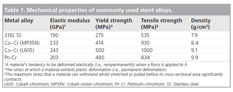
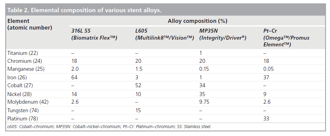
Initially almost all stents were made from 316L stainless steel, and this is still utilized in some stent platforms today due to its favorable mechanical properties [2]. Cobalt–Nickel– Chromium, Cobalt–Chromium and more recently Platinum–Chromium metal alloys have been introduced amongst others. The advantages of these alloys include higher yield strength (Table 1) [13]. Although of less clinical relevance in the DES era, in several randomized trials thinner struts have also been shown to reduce both angiographic and clinical restenosis [14,15]. More importantly, thinner struts reduce the overall crossing profile of the stent significantly improving deliverability. Furthermore, with the increasing prevalence of obesity as well as percutaneous treatment of highly calcific coronary stenoses, recently developed metal alloys have a higher radio-opacity, enabling precise positioning in these difficult clinical situations. Radio-opacity is proportional to the cube of an element’s atomic number [16]. Table 2 shows the atomic composition of several contemporary stent platforms. Comprising of 33% platinum (atomic number 78), the Promus/Taxus Element™ (Boston Scientific, MA, USA) stent platform is significantly more visible than other stent platforms.
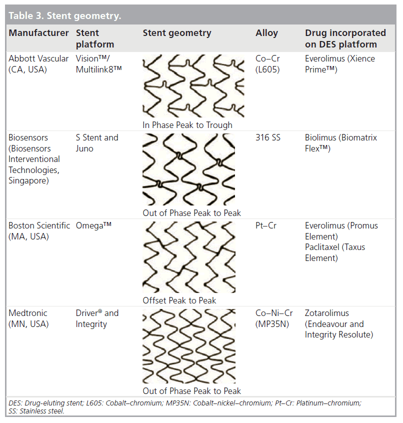
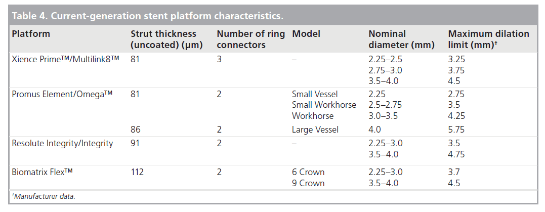
The geometry of the stent cell structure, the connectors between rings/cells and the resultant metal:artery ratio are the most widely variable aspect of stent design across current manufacturers. Three basic stent geometries are currently utilized in the four most commonly implanted stent platforms in the UK (Table 3). As well as affecting the deliverability of the stent, these configurations affect the mechanical properties of the platform. Of particular interest to the clinician is the maximum achievable diameter of the stent on postdilation. As summarized in Table 4 this maximal diameter can vary by more than 1 mm in the largest diameter stents depending on which platform is used.
Longitudinal stent strength
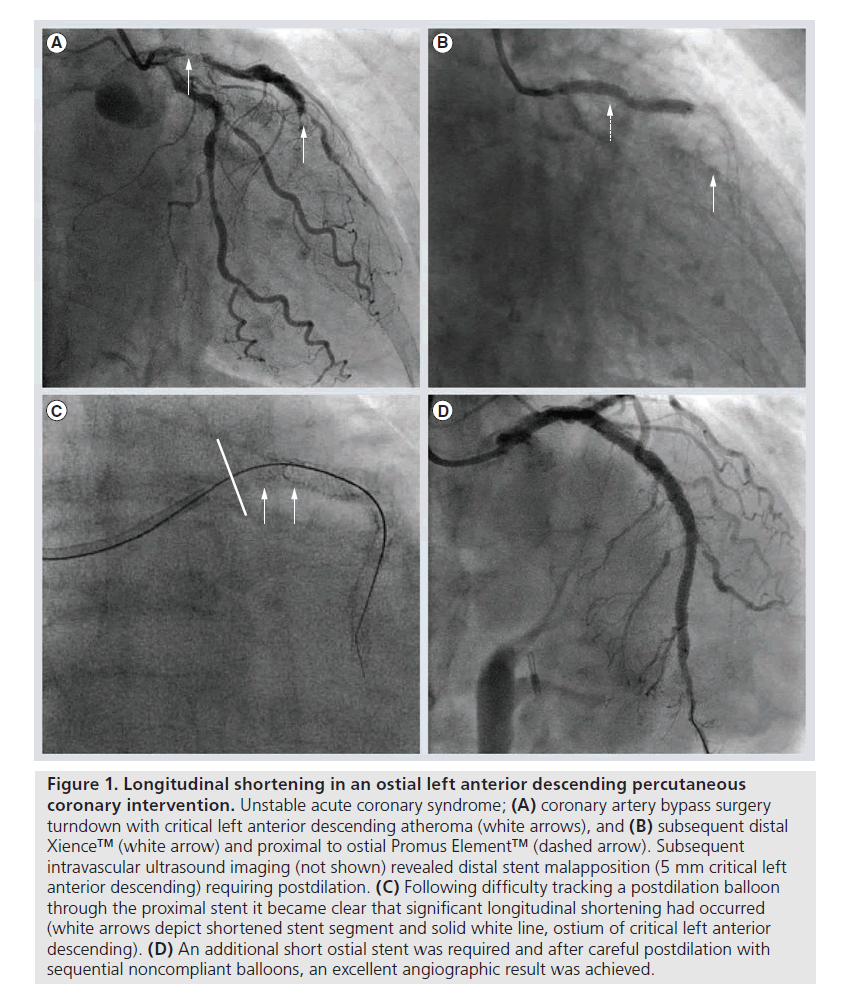
Until recently, this mechanical property of coronary stents had not been reported as it has been seen to be unimportant, given the primary role of a stent to provide radial support to the vessel endothelium. However, recent reports by Hanratty and Walsh and Pitney et al. have highlighted the phenomenon of longitudinal stent compression, or pseudofracture, that can occur when a stent is traversed by other devices such as the tip of a guiding catheter, postdilation balloon, further stent or indeed any other device [17,18]. If this is left unrecognized a potential nidus for stent thrombosis will remain. This may not always be immediately apparent on angiographic assessment, despite dramatic appearances with adjunctive imaging modalities such as intravascular ultrasound or optical coherence tomography [17].
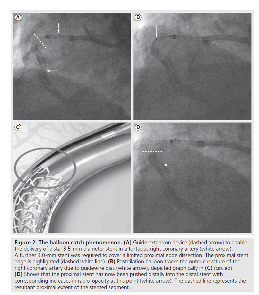
There are certain technical scenarios that are much more likely to contribute to longitudinal stent compression. These include the treatment of aorto-ostial disease, where the guiding catheter will be in close proximity to the deployed stent platform throughout the case [17]. The situation is even more likely to occur when the ostium of the left main coronary requires treatment as the immediately deployed stent will often not be large enough to be apposed to the vessel wall until it has been aggressively postdilated. Our own experience suggests that well expanded, adequately sized and well apposed stents are very unlikely to be compressed by secondary coronary devices. However, there is a ‘perfect storm’ that can occur when a slightly undersized or under-deployed proximal stent edge can be distorted by secondary devices, especially stiff and bulky postdilation balloons. This phenomenon of ‘balloon catch’ is more likely to occur in a tortuous vessel, when the guide wire will bias towards the outer curvature of the vessel and direct other devices towards the proximal portion of the already deployed stent (Figures 1 & 2). Trapped guidewires that are jailed behind deployed stents may exacerbate the risks of a balloon catch phenomenon.
Figure 1. Longitudinal shortening in an ostial left anterior descending percutaneous coronary intervention. Unstable acute coronary syndrome; (A) coronary artery bypass surgery turndown with critical left anterior descending atheroma (white arrows), and (B) subsequent distal Xience™ (white arrow) and proximal to ostial Promus Element™ (dashed arrow). Subsequent intravascular ultrasound imaging (not shown) revealed distal stent malapposition (5 mm critical left anterior descending) requiring postdilation. (C) Following difficulty tracking a postdilation balloon through the proximal stent it became clear that significant longitudinal shortening had occurred (white arrows depict shortened stent segment and solid white line, ostium of critical left anterior descending). (D) An additional short ostial stent was required and after careful postdilation with sequential noncompliant balloons, an excellent angiographic result was achieved.
Figure 2. The balloon catch phenomenon. (A) Guide extension device (dashed arrow) to enable the delivery of distal 3.5-mm diameter stent in a tortuous right coronary artery (white arrow). A further 3.0-mm stent was required to cover a limited proximal edge dissection. The proximal stent edge is highlighted (dashed white line). (B) Postdilation balloon tracks the outer curvature of the right coronary artery due to guidewire bias (white arrow), depicted graphically in (C) (circled). (D) Shows that the proximal stent has now been pushed distally into the distal stent with corresponding increases in radio-opacity at this point (white arrow). The dashed line represents the resultant proximal extent of the stented segment.
Factors contributing to stent compression
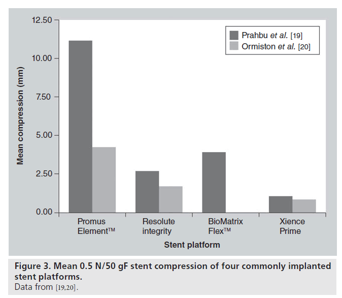
Although a significant conflict of interest may exist, Abbott Vascular, CA, USA recently investigated the longitudinal compressive properties of a selection of commonly implanted stents [19]. Subsequently, 14 × 3.0 mm diameter, 28–30 mm length stent platforms were balloon expanded to nominal pressure and mounted on mandrills. Each was then subjected to 50 gF or 0.5 N uniform compressive force and mm change in length was observed. All stents exhibited longitudinal compression at this force. However, the Promus Element stent was seen to exhibit, on average, a more dramatic shortening of 13 mm. It must be noted that potentially clinically relevant shortening was seen to occur with all platforms and at compressive forces lower than 50 gF. There was no correlation between strut thickness and degree of longitudinal compression (correlation coefficient, r = -0.10), and metal alloy appears to be less relevant with regards to longitudinal strength than stent geometry. Indeed, the main conclusion from the paper was that the crucial determinant of susceptibility to longitudinal compression was the number of connectors between rings and their exact geometrical arrangement (Figure 3).
Recently, Ormiston et al. have also performed an independent bench test of a selection of commonly implanted stents to compare their longitudinal compressive and elongatory properties [20]. The method of compressive testing was similar. A uniform 0.5 N force was applied to all stents (equivalent to 51 gF) and the compression was measured. The observed results are quite different to those of the Abbott study, although the Omega™ (Boston Scientific, MA, USA)/Promus Element platform is still seen to exhibit greater shortening at this force (Figure 3). An important point of difference in the testing method may account for this variation. In the investigation by Ormiston et al., each stent was clamped so that only 10 mm of stent was freely compressed by the Instron device, whereas in the previously described study, 28–30 mm stents were not clamped and the compressive force was therefore applied to the whole stent. In our opinion the bench tests by Ormiston et al. are more representative of clinical scenarios.
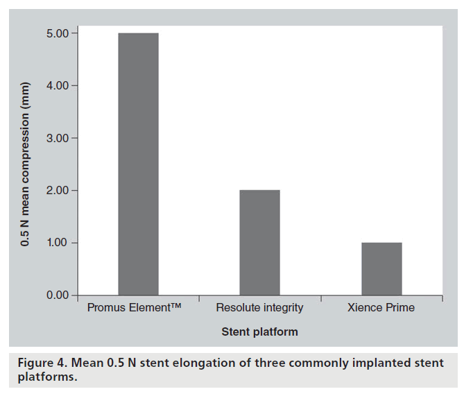
To investigate the force required to elongate the selected stents, 3.00 mm stents were clamped exposing 8 mm of stent. A hook was placed through the third ring/hoop of the stent and attached to the force generator. Elongation was plotted against force. On this test both the Omega/Promus Element and Driver® (Medtronic, MN, USA) stents were the most susceptible to elongation with dramatic macroscopic deformation visible with 0.5 N elongation force. Once again, a similar conclusion was reached that the crucial determinant of susceptibility to longitudinal compression and elongation was the number of connectors between rings and their exact geometrical arrangement (Figure 4).
Contextualising force generation
In vivo, the force generated to compress or elongate a stent will arise from a combination of factors. Guide catheters exhibit varying degrees of ‘backup support’ or force when engaging a coronary artery. Deeply intubating the guide into a ‘power’ position increases this force, as does excessive guide catheter movement into and out of the coronary ostium. This is of obvious relevance with ostial and proximal vessel stenting.
Predating the concept of longitudinal stent deformation, a Japanese group investigated the force generated by a selection of coronary guiding catheters when engaging both the left and right coronary arteries [21,22]. In a synthetic replica of the arterial tree, coronary arteries were engaged from both femoral and right and left radial arteries. As would be expected, backup force is higher when femoral rather than transradial access is used, with larger French guide catheters and when catheters designed for extra backup are used. Over 130 gF is generated using an 8F JL4 from the femoral approach and the commonly used 6F EBU/XB catheter from the right radial approach will create over 60 gF. When engaging the right coronary artery from the right radial artery, over 50 gF is generated using a 6F JR catheter. However, vastly larger forces can be generated by deliberately forcing guide catheters into the coronary, particularly if balloon anchors are used. Finally, it should also be remembered that:
Force = mass × acceleration
and that more rapid aggressive maneuvers using guide catheters (or catheter extension systems) could be capable of generating over 500 gF or 5 N. These forces will certainly grossly distort any coronary stent.
Additionally, although bench testing applies a uniform force to a stent, guidewire bias and nonuniform stent apposition will usually focus force on a small section of stent greatly increasing the potential for deformation with these relatively low forces. For example, if a 0.5 N force is equally spread across five crowns of a stent, then only 0.1 N is applied at each point of contact. However, if the entire force is applied at one single point on the stent, then the potential for deformation is greatly increased. In addition, stent delivery was historically routinely tested at forces in excess of 300 gF. These bench test models were designed to mimic tortuous calcific vessels that created very large amounts of friction and demonstrated that these devices could be delivered safely at relatively large forces. It is therefore obvious that in difficult clinical scenarios, very large forces can be delivered into the coronary. If such excessive forces are applied, then it is very likely that any modern stent platform can be deformed longitudinally.
Frequency of longitudinal stent deformation
Estimating the frequency of longitudinal stent deformation is hampered by the limitations of conventional cine-angiography to detect the phenomenon. Additionally, whilst the platinum–chromium Element/Omega stent may be more susceptible to compressive forces, it is also a far more visible stent platform and therefore recognition of compression/elongation is likely to be more straightforward. In contrast, the very thin strut Cobalt–Chromium platforms can be difficult to visualize and there is a significant potential for stent deformation to be missed with these devices. In our own published case series, one ‘concertina stent’ was only detected with routine intravascular ultrasound following left mainstem intervention [17].
Further case reports and case series have emerged that also document longitudinal stent compression [23,24]. This phenomenon has also received significant attention at international conferences and in the media. There will be increasing awareness amongst cardiologists and it is likely that there will be a significant rise in the number of reports of this complication over the coming months-to-years. Systematic reporting should lead to a more reliable estimation of the overall incidence of longitudinal stent deformation. Retrospective analyses from angiographic core laboratoriess are also occurring that will re-examine whether any cases can be examined retrospectively in previous clinical investigations and add to our knowledge base.
Clinical sequelae of longitudinal stent compression
Failure of stent strut endothelialization and strut malapposition are thought to be contributory factors in the pathogenesis of stent thrombosis [25]. Stent malapposition can occur through a variety of mechanisms including positive remodeling of the stented vessel, stent undersizing and thrombus resorption. Longitudinal stent compression can result in grossly malapposed stent struts that create a nidus for stent thrombosis and, as the cases published by Williams et al. and Robinson et al. indicate, stent thrombosis can occur when this complication has not been identified and/or treated [23,24]. At present, it is unclear what proportion of stent thrombosis events are due to this phenomenon. However, the absence of reports of this mechanism for stent thrombosis in large international registries suggests that this event is truly very rare. Indeed stent thrombosis is becoming an increasingly rare event with the application of modern DES platforms [26].
Management of longitudinal stent deformation
A well-apposed stent is very unlikely to undergo longitudinal compression/elongation as friction from the arterial wall will counteract compressive and elongatory forces. Therefore, well-sized initial stent implantation and careful postdilation balloon tracking with proximal stent optimization are essential. This is of particular importance when treating the left main coronary artery. Data from our Northern Irish population suggest that on average, the maximal vessel diameter of the left main coronary artery assessed by intravascular ultrasound is 5.56 mm [27]. Therefore, in order to achieve stent apposition and prevent possible longitudinal compression, large postdilation balloon sizes should be considered, especially for male patients. Furthermore the choice of stent platform is key in this situation. Of the four commonly implanted stent platforms, only the Promus/Taxus Element has manufacturer data to support dilation beyond 5.5 mm. In addition, we have changed our practice towards the use of softer semi-compliant balloons for the initial postdilation of stents that we anticipate are mismatched to larger vessels.
Guide catheter selection is also crucial. Certain catheters are well known to deeply engage the left coronary artery and it is for this reason they give excellent backup support. However, if stenting ostial or very proximal lesions, compromising guide catheter support for the ability to back out the guide easily may be advisable. When removing long balloons or side branch wires, similar care with the guide catheter must be taken, in order to avoid deep intubation of the coronary artery.
If it is apparent that longitudinal compression has occurred, careful postdilation is required. To recross a damaged stent may require very small diameter balloons with a low crossing profile, followed by gradual upsizing. If through damage to the stent, treatment of the vessel itself has been compromized, further stent implantation may be required, but is not in all instances necessary if the final angiographic result is acceptable [17]. Indeed it may be advisable to try and avoid further stent implantation as the ‘concertina’ stent overlapped with further stents will result in multiple layers of overlapping stent struts leading to delayed endothelialization and may increase the resultant risk of late stent thrombosis.
Repeat cardiac catheterization of patients with ostial right coronary artery or left main stem stents should be performed with extreme care as the stent may well overhang into the aorta and be easily compressed. If wiring of the vessel is required in these situations then the floating wire technique is advisable (wiring the vessel from a nonengaged guiding catheter). Once a guide wire is in the distal vessel the guide catheter can safely be advanced coaxially into the vessel if required.
Lesion-specific percutaneous coronary intervention
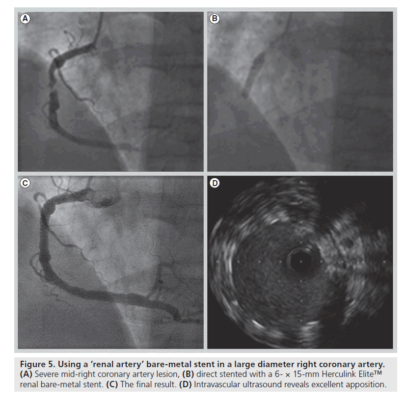
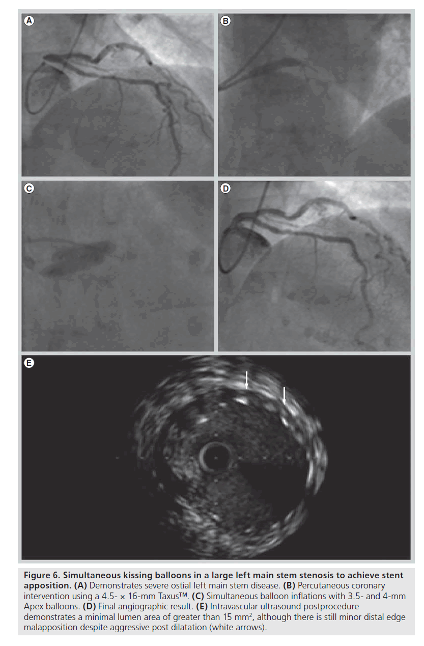
As it has become apparent that initial stent malapposition without prompt proximal optimization risks longitudinal stent compression, it is now recognized that we must individualize the percutaneous management of our patients which, in part, requires an up to date understanding of available stent platforms and their mechanical properties. The increasing frequency of left main coronary stenting illustrates this issue perfectly; postdilation of the stent well beyond nominal diameter is often required in order to achieve apposition of the stent with the vessel wall and prevent potentially fatal stent thrombosis due to stent malapposition. We have successfully treated low tertile syntax score patients with left main disease using the Herculink Elite™ (Abbott Vascular) bare-metal renal artery stent, which is available in diameters up to 7 mm that can be postdilated to 8 mm, as well as with a conventional coronary stent post dilated with the side-by-side double balloon technique in order to achieve stent apposition (Figures 5 & 6). Given the European Society of Cardiology IIa recommendation for left main stenting, the development of stent platforms more suited to this application will be pertinent in the future [28].
Figure 5. Using a ‘renal artery’ bare-metal stent in a large diameter right coronary artery. (A) Severe mid-right coronary artery lesion, (B) direct stented with a 6- × 15-mm Herculink Elite™ renal bare-metal stent. (C) The final result. (D) Intravascular ultrasound reveals excellent apposition.
Figure 6. Simultaneous kissing balloons in a large left main stem stenosis to achieve stent apposition. (A) Demonstrates severe ostial left main stem disease. (B) Percutaneous coronary intervention using a 4.5- × 16-mm Taxus™. (C) Simultaneous balloon inflations with 3.5- and 4-mm Apex balloons. (D) Final angiographic result. (E) Intravascular ultrasound postprocedure demonstrates a minimal lumen area of greater than 15 mm2, although there is still minor distal edge malapposition despite aggressive post dilatation (white arrows).
Discussion
The complex interaction between metal alloy, strut thickness, stent geometry and stent-balloon platform results in a variety of performance characteristics across the commonly implanted stent platforms that are currently available. Rather than trying to pick the ‘best stent’ we suggest that a ‘one stent fits all’ philosophy is no longer appropriate. Today’s interventional cardiologist should aim to select a coronary stent with performance characteristics suited to the anatomy to be treated.
For example, if a stent comes back from the proximal left anterior descending coronary artery to a large left main coronary, an appropriate stent should be selected that can be safely over-expanded to match the larger proximal vessel diameter and adequately appose the device. Similarly, where guide catheter position may compromise the integrity of a proximal stent, the operator should adjust their technique and make every effort to prevent proximal stent compression. Despite this, just as stent engineering is a science of compromise, the perfect combination of stent characteristics is not available for the particular anatomy that is to be treated and compromises must be made.
In these situations the operator’s skill and judgment are required to ensure that despite the engineering limitations of the chosen platform, complications do not arise. That longitudinal compression has not been reported in large international multicenter trials and registries highlights not only the level of expertise of many interventional cardiologists but also that despite the engineering compromises, today’s coronary stent platforms are excellent devices.
Future perspective
Engineering developments to improve the longitudinal strength of a given stent are likely to become a normal feature that is tested, designed for and reported in standard data. It is now apparent that as the practice of interventional cardiology evolves, the way in which coronary stents are designed must now change to reflect these new realities. The pursuit of increasingly deliverable devices should now be altered towards seeking devices that are more stable in increasingly demanding engineering contexts. This will not compromise the efficacy of these devices, a feature that is much more related to the drug eluted from the device. Therefore, efficacy need not be compromized, but stent design certainly needs to return to the fore.
Executive summary
▪ The primary role of a coronary stent is to provide radial support to the vessel wall, increasing the maximal luminal diameter, allowing normal flow. Other desirable characteristics include flexibility, low crossing profile and high visibility.
▪ Recently, longitudinal compression and elongation of coronary stents has been recognized.
▪ Longitudinal compression and elongation is related to stent geometry. Reductions in the number of connectors between rings and nonparallel orientation of connectors with respect to a stent’s long axis seem to be the primary determinants of a stent’s mechanical propensity to compression and elongation.
▪ Forces generated during routine percutaneous coronary intervention are clearly sufficient to deform all stents to a greater or lesser degree.
▪ When selecting a stent for the treatment of ostial or very proximal disease, or when the treatment of very large vessels is required, appreciation of the mechanical properties of the stent platform is required.
▪ Novel techniques or stent platforms may be required to facilitate optimal treatment of specific coronary anatomy and thus avoid longitudinal compression and/or malapposition.
Financial & competing interests disclosure
The authors have no relevant affiliations or financial involvement with any organization or entity with a financial interest in or financial conflict with the subject matter or materials discussed in the manuscript. This includes employment, consultancies, honoraria, stock ownership or options, expert testimony, grants or patents received or pending, or royalties.
No writing assistance was utilized in the production of this manuscript.
References
Papers of special note have been highlighted as:
▪▪ of considerable interest
- Sigwart U, Puel J, Mirkovitch V, Joffre F, Kappenberger L. Intravascular stents to prevent occlusion and re-stenosis after transluminal angioplasty. N. Engl. J. Med. 316(12), 701–706 (1987).
- Colombo A, Stankovic G, Moses JW. Selection of coronary stents. J. Am. Coll. Cardiol. 40(6), 1021–1033 (2002).
- de Feyter PJ, Kay P, Disco C, Serruys PW. Reference chart derived from post stentimplantation intravascular ultrasound predictors of 6-month expected restenosis on quantitative coronary angiography. Circulation 100(17), 1777–1783 (1999).
- Cutlip DE, Chauhan MS, Baim DS et al. Clinical restenosis after coronary stenting: perspectives from multicenter clinical trials. J. Am. Coll. Cardiol. 40(12), 2082–2089 (2002).
- Greenberg D, Bakhai A, Cohen DJ. Can we afford to eliminate restenosis? Can we afford not to? J. Am. Coll. Cardiol. 43(4), 513–518 (2004).
- Chen M, John J, Chew D, Lee D, Ellis S, Bhatt D. Bare-metal stent restenosis is not a benign clinical entity. Am. Heart J. 151(6), 1260–1264 (2006).
- Doyle B, Rihal CS, O’Sullivan CJ et al. Outcomes of stent thrombosis and restenosis during extended follow-up of patients treated with bare-metal coronary stents. Circulation 116(21), 2391–2398 (2007).
- Nayak AK, Kawamura A, Nesto RW et al. Myocardial infarction as a presentation of clinical in-stent restenosis. Circ. J. 70(8), 1026–1029 (2006).
- Stone GW, Ellis SG, Colombo A et al. Offsetting impact of thrombosis and restenosis on the occurrence of death and myocardial infarction after paclitaxel-eluting and bare-metal stent implantation. Circulation 115(22), 2842–2847 (2007).
- Serruys PW, Morice MC, Kappetein AP et al. Percutaneous coronary intervention versus coronary-artery bypass grafting for severe coronary artery disease. N. Engl. J. Med. 360(10), 961–972 (2009).
- Serruys PW, Silber S, Garg S et al. Comparison of zotarolimus-eluting and everolimus-eluting coronary stents. N. Engl. J. Med. 363(2), 136–146 (2010).
- Stone GW, Midei M, Newman W et al. Randomized comparison of everolimuseluting and paclitaxel-eluting stents. Circulation 119(5), 680–686 (2009).
- O’Brien BJ, Stinson JS, Larsen SR, Eppihimer MJ, Carroll WM. A platinum–chromium steel for cardiovascular stents. Biomaterials 31(14), 3755–3761 (2010).
- Pache J, Kastrati A, Mehilli J et al. Intracoronary stenting and angiographic results: strut thickness effect on restenosis outcome (ISAR-STEREO-2) trial. J. Am. Coll. Cardiol. 41(8), 1283–1288 (2003).
- Kastrati A, Mehilli J, Dirschinger J et al. Intracoronary stenting and angiographic results: strut thickness effect on restenosis outcome (ISAR-STEREO) trial. Circulation 103(23), 2816 –2821 (2001).
- Finet G, Rioufol G. Coronary Stent Longitudinal deformation by compression: is this a new global stent failure, a specific failure of a particular stent design or simply an angiographic detection of an exceptional PCI complication? Eurointervention pii: 20111104-00 (Epub ahead of print) (2011).
- Hanratty C, Walsh S. Longitudinal compression: a “new” complication with modern coronary stent platforms – time to think beyond deliverability? Eurointervention 7(7), 872–877 (2011).
- Pitney M, Pitney K, Jepson N et al. Major stent deformation/pseudofracture of 7 Crown Endeavor/Micro Driver stent platform: incidence and causative factors. Eurointervention 7(2), 256–262 (2011).
- Prabhu S, Schikorr T, Mahmoud T, Simonton C. Engineering assessment of the longitudinal compression behaviour of contemporary coronary stents. Eurointervention pii: 20111103-00 (Epub ahead of print) (2011).
- Ormiston JA, Webber B, Webster MW. Stent longitudinal integrity: bench insights into a clinical problem. JACC Cardiovasc. Interv. 4(12), 1310–1317 (2011).
- Ikari Y, Nagaoka M, Morino Y, Tanabe T. The physics of guiding catheters for the left coronary artery in transfemoral and transradial interventions. J. Invasive Cardiol. 17(12), 636–641 (2005).
- Ikari Y, Masuda N, Matsukage T, Morino Y. Backup force of guiding catheters for the right coronary artery in transfemoral and transradial interventions. J. Invasive Cardiol. 21(11), 570–574 (2009).
- Williams P, Mamas M, Morgan K, Fraser D. Longitudinal stent deformation: a retrospective analysis of frequency and mechanisms. Eurointervention pii: 20111018-02 (Epub ahead of print) (2011).
- Robinson AD, Schreiber TL, Sobh MA, Grines CL. Deformation, longitudinal shortening, and accordion of an ion stent. J. Interv. Cardiol. 24(6), 493–495 (2011).
- Cook S, Wenaweser P, Togni M et al. Incomplete stent apposition and very late stent thrombosis after drug-eluting stent implantation. Circulation 115(18), 2426–2434 (2007).
- Sarno G, Lagerqvist B, Frobert O, Nilsson J, Olivecrona G, Omerovic E. Lower risk of stent thrombosis and restenosis with unrestricted use of “new generation” drug-eluting stents: a report from the nationwide Swedish Coronary Angiography and Angioplasty Registry (SCARR). Eur. Heart J. 33(5), 606–613 (2012).
- Shand J, Walsh S. An intravascular ultrasound anatomical study of the distal left mainstem and proximal left anterior descending arteries in a Northern Irish population. Ir. J. Med. Sci. 179(Suppl. 10), S393 (2010).
- Wijns W, Kolh P, Di Mario C et al. Guidelines on myocardial revascularization. Eur. Heart J. 31, 2501–2555 (2010).
▪▪ The first report of longitudinal compression.
▪▪ The first report of longitudinal stent elongation.
▪▪ An independent bench test investigating the tendency to longitudinal deformation of several commonly implanted stents.
