Review Article - Interventional Cardiology (2012) Volume 4, Issue 3
Examining the use of imaging during T-AVI: focus on online 3D DynaCT
- Corresponding Author:
- Thomas Walther
Department of Cardiac Surgery
Kerckhoff Heart Center, Bad Nauheim, Germany
Tel: +49 6032 996 2502
Fax: +49 6032 996 2567
E-mail: t.walther@kerckhoff-klinik.de
Abstract
Keywords
3D imaging,computed tomography,DynaCT,echocardiography,imaging,rotational angiography,transcatheter aortic valve implantation
Introduction
Transcatheter aortic valve implantation (T-AVI) is globally accepted as an alternative treatment option for elderly high-risk patients suffering from aortic valve stenosis. The outcomes after T-AVI have improved over recent years and early survival rates above 90% can be achieved in high-risk patients [1–5]. T-AVI is performed via a retrograde transfemoral [6] or an antegrade transapical [7] approach, although more recently a direct aortic approach has also been used. T-AVI is usually performed in a fully equipped hybrid operating room or in a special catheterization laboratory. In parallel to all conventional surgical equipment and heart lung machine support, specific imaging such as transesophageal echocardiography (TEE) as well as high quality fluoroscopy and angiography should be available.
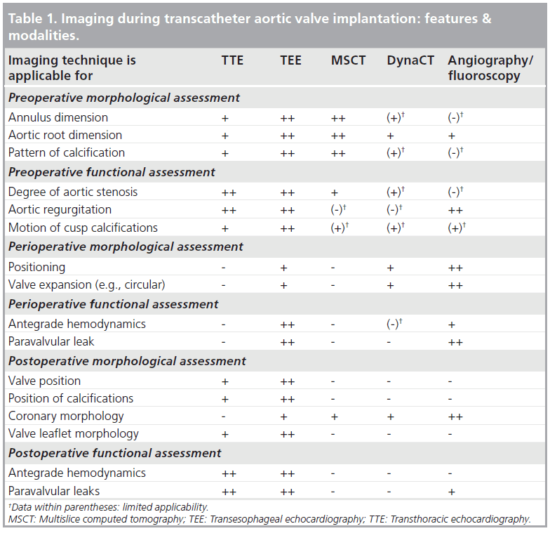
Since T-AVI is a closed chest procedure, the typical direct vision of the diseased valve during conventional aortic valve replacement is missing. To compensate for the lack of direct vision, optimal imaging is of major importance during T-AVI. Imaging is important for preoperative, perioperative and postoperative morphological and functional visualization and assessment, as detailed in Table 1. As such, after perfect imaging, individual decisions on size, device and access selection can be taken for the individual patient.
Current preoperative imaging includes transthoracic echocardiography (TTE) and TEE, as well as multislice computed tomography (MSCT) and routine coronary angiography to exclude any concomitant coronary artery disease. Precise preoperative measurements of the native valve are indispensable because aortic annulus sizes that are too small or too large cannot be treated with T-AVI and a chosen valve that is too large or too small can lead to major intraprocedural complications, such as annular rupture or severe paravalvular leakage and valve embolization. Intraprocedural imaging includes TEE and 2D fluoroscopy/angiography. Both imaging techniques are used for valve prosthesis positioning and assessment of valve prosthesis function. Due to the fact that T-AVI is a relatively new procedure, improvements in the technique itself, but especially improvements in imaging techniques are still ongoing.
The scope of this manuscript is the use of intraoperative rotational angiography C-arm computed tomography imaging. The focus is the so-called DynaCT (Siemens AG, Forchheim, Germany) as one of the new imaging techniques to ease T-AVI.
Background
▪ Why is imaging so important for T-AVI?
Conventional aortic valve replacement using cardiopulmonary bypass and cardioplegic arrest allows for a direct view to the native valve. Sizing of the aortic annulus and prosthesis choice are performed intraoperatively and special anatomic characteristics can be directly considered during the procedure. Furthermore, conventional aortic valve prostheses are available in a large number of different sizes and configurations, which allows for treatment of every aortic annulus diameter. In case of an annulus that is too small, a root enlargement procedure can be performed. The current available T-AVI prostheses only allow for treatment of aortic annulus diameters between 19 and 28 mm and due to the lack of intraoperative direct vision of the native valve, the prosthesis size has to be chosen preoperatively. Patients with an annulus that is too large or too small have to be excluded from T-AVI. The accuracy of the prosthesis size is fundamental because the tolerance for deviation is limited. Implantation of a prosthesis that is too small leads to significant paravalvular leaks and, at worst, to embolization of the prosthesis. Implantation of a prosthesis that is too large can lead to annular rupture [3,8], which requires immediate conversion to sternotomy and use of cardiopulmonary bypass to either repair or replace the aortic root. Another potential complication during T-AVI is an occlusion of the coronary ostia by either native calcification or the prosthesis [9–11]. To avoid this, the distance between the aortic annulus and coronary ostia should be known preoperatively; any diameter of at least 9 mm or above is considered safe.
During the T-AVI procedure there are also some major steps that require precise imaging. After transapical advancing of the guidewire it has to be determined whether it is caught in the mitral valve chords. During implantation, optimal angulation of the C-arm will be perpendicular to the level of the aortic annulus. In order to find this, perpendicular angulation fluoroscopy/angiography is used. After valve implantation the valve function is assessed to indentify potential aortic regurgitation or malpositioning of the valve.
The two routinely used T-AVI valves are the Medtronic CoreValve® (Medtronic, MN, USA) and the Edwards SAPIEN XT™ (Edwards Lifesciences, CA, USA). The Medtronic CoreValve is a porcine pericardial valve mounted on a self expandable nitinol stent. It is available in three sizes (26, 29 and 31 mm). It allows for retrograde implantation only. Due to its ‘open mesh’ design in the area of the native coronary ostia, coronary occlusion is rarely described. The Edwards SAPIEN XT prosthesis consists of bovine pericardial leaflets mounted on a balloon-expandable cobalt-chromium stent. It is available in the sizes 23, 26 and 29 mm and can be implanted either using the retrograde transfemoral or the antegrade transapical approach.
▪ Current preoperative imaging
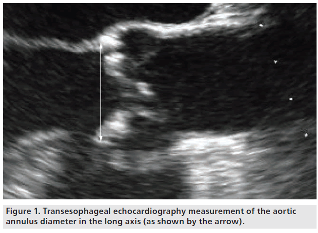
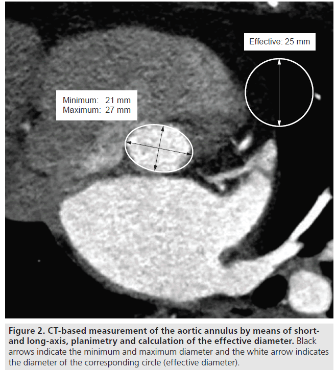
Since the beginning of T-AVI, echocardiography is the domain for aortic annulus sizing, either by TTE or by TEE. Measurements should be performed in a long-axis view at mid-systole. The diameter should be measured at the insertion of the native cusps, including all calcifications (Figure 1) [12,13]. The measurement should be performed several times to avoid errors due to incorrect adjustment of the axis. With the growing experience in T-AVI, the complex 3D geometry of the aortic annulus has become a focus. The aortic annulus shows a circular geometry only in the minority of patients. Usually it is more oval shaped [14–17], which leads to underestimation of the ‘true’ diameter using 2D echocardiography. First experiences with aortic annulus sizing in 3D TEE show promising results with regards to obtaining more precise measurements [18–20], but the main disadvantage of this technique is that it is not routinely available in every hospital. Another 3D imaging technique that is available in most centers, which is thus being routinely used for T-AVI screening, is MSCT. MSCT offers the opportunity of a 3D view of the aortic annulus and allows for measurements in the annular plane. The aortic annulus in MSCT is defined as the most caudal attachment of the three native aortic cusps (so-called nadirs) [15,21] and is commonly visualized in a double oblique transverse view (Figure 2). The minimum and maximum aortic annulus diameter can be measured, but in the more common oval-shaped annuli the minimum and maximum diameter strongly differ and a proper prosthesis size choice would thus be difficult. The recently introduced concept of measuring the ‘effective diameter’ [21–23] seems to be more accurate for prosthesis size choice. For calculating the ‘effective diameter’, the luminal circumference of the aortic annulus is measured and the resulting area is calculated. The equation for the area of a disk:
Figure 1: Transesophageal echocardiography measurement of the aortic annulus diameter in the long axis (as shown by the arrow).
Disk area = p × r2
is now used to calculate the diameter of a disk with the same area (Figure 2):
Effective diameter = 2 × √(circumferential area/p)
Initially, MSCT was included into the routine screening protocol for T-AVI patients; it was used to screen the femoral and iliac access vessels for potential stenosis, kinking and calcifications to allow for a transfemoral access, as well as to visualize the aorta and its calcification to measure the distance between the aortic annulus and the coronary ostia. For coronary distance assessment, again the aortic annulus plane is visualized and the distance is measured up to the caudal insertion of the left main stem and the right coronary artery. This distance can also be measured using 3D TEE [18].
MSCT also allows for preoperative estimation of the later intraoperative angulation perpendicular to the aortic annulus [24]. The predicted angulation has to be finally controlled by aortic root angiography because patient positioning during MSCT and during T-AVI often differs and thus lacks registration.
Routine preoperative coronary angiography is performed to detect potential coronary artery disease and, during the coronary angiography, a contrast agent application in the abdominal aorta can also detect kinking of the femoral arteries. Some centers also use conventional angiography for aortic annulus sizing [18,25]. It shows good agreements with echocardiographic measurements, but is just limited to the 2D plane.
▪ Current perioperative imaging
The most important peri-/intra-operative imaging tool is transesophageal echo and fluoroscopy/ angiography. In general, fluoroscopy is used to control any wire advancing and manipulation. The perpendicular view to the aortic annulus is achieved by performing several aortic root angiographies. A helpful start angulation is left anterior oblique 10° cranial 10° [12]. After performing the first aortic root angiography in this angulation, further adjustments can be performed if required until all three aortic valve cusps are in one plane. MSCT can also be used to preoperatively estimate the ideal angulation to obtain orthogonal visualization of the aortic root [26]. Another root angiography is performed during balloon valvuloplasty to visualize the coronary ostia and final deployment of the valve prosthesis is also performed under fluoroscopy to control the positioning and correct the position if necessary. After valve implantation, a final root angiography is performed to exclude significant transvalvular or paravalvular leakage.
Some new-generation T-AVI prostheses allow for anatomical orientation of the valve, meaning the stent commissures can be aligned with the native commissures. Visualizing the stent commissures by fluoroscopy controls the anatomical orientation.
Intraoperative TEE is used to assess hemodynamic function at any time necessary. After transapical advancing of the guidewire, TEE is used to assess if the guidewire is accidently caught in the mitral valve apparatus. Prosthesis function can be controlled immediately after implantation by TEE. Fully TEE-guided T-AVI procedures are described [27,28], but T-AVI using fluoroscopy/angiography is still routine.
Another exceptional situation involves transfemoral aortic valve implantation under local anesthesia without intraoperative TEE, but with TTE intraprocedural functional assessment.
Focus on 3D DynaCT
▪ Introduction of DynaCT
With the term ‘DynaCT’ the generation of a 3D CT-like image of any target structure using a C-arm (Artis zee/zeego with a dedicated workstation, Siemens AG, Forchheim, Germany) of a fixed angiography unit. Within this article we focus on DynaCT generation of the aortic root during T-AVI. DynaCT is a proprietary development of Siemens AG. Several hundred 2D x-ray images are acquired by a 200° rotational angiography with a flat-panel detector. Due to high-resolution optimized detectors, the spatial resolution of DynaCT is very high (up to 0.1–0.2 mm with high resolution protocols). The appropriate software automatically reconstructs 3D data from the acquired rotational image sequence. The temporal resolution of an isolated rotational angiography without 3D reconstruction equals the frames per second.
The workstation can be controlled by the operator directly from table. Every single 3D image from the workstation can be overlaid on the real-time fluoroscopy screen. The system allows for direct flow of information between the workstation and the angio system. Any virtual rotation of the volume on the workstation by the operator can be transmitted to the angio system and the angio system moves the C-arm to the new position. This workflow also functions the other way around. Any changes of C-arm angulation can be transmitted to the workstation and the 3D image rotates to the new angulation. Furthermore, it is possible to import other 2D or 3D image data into the workstation (e.g., preoperative MSCT data). 2D/3D image fusion technique enables overlay to live fluoroscopy. This fusion technique can be used to integrate preoperative planning data into the intraprocedural workflow.
▪ Initial use of DynaCT
First experience with DynaCT was gained in neuroendovascular imaging; for example, it is possible to visualize cerebral aneurysms for interventional procedures [29,30]. Meanwhile, the indication for DynaCT has broadened and it is used for endovascular aortic repair [31,32], for imaging during interventional antiarrhythmic therapy [33,34] and in orthopedic spine surgery [35].
▪ DynaCT during T-AVI
Initial experiences of DynaCT during T-AVI have recently been published [36–41]. These are predominantly feasibility trials and descriptive studies regarding the first generations of DynaCT during T-AVI. Comparative studies about DynaCT versus MSCT and angiography are just being performed and will be published soon. In summary, DynaCT eases some major steps of T-AVI imaging and even provides some new tools.
To acquire the raw dataset, the table is adjusted in a special way, such that the aortic root is in the isocenter of the detector. After table adjustment, all additional patient movements are stopped by using rapid ventricular pacing (no ventricle output) and by stopping patient ventilation. Via the pigtail catheter in the aortic root, only 15 ml of contrast agent (diluted with saline to a total of 75 ml) is injected over 5 s and the 200° rotational angiography is started with a 1 s delay to the contrast agent application. This low amount of contrast agent allows for sufficient contrast of the aortic root due to the fact that rapid ventricular pacing is used during image acquisition, thus the contrast remains in the aortic root for a short period of time. By this special technique renal function of the patient can be maximally preserved. ECG-gated data acquisition is also possible. Disadvantages include the need for multiple rotations of the C-arm and a clearly larger amount of contrast agent because the contrast agent will be washed out by the ventricular output. For T-AVI, the rapid pacing protocol with low contrast agent dose provides all information with excellent image quality. The effective organ dose is approximately 2.4 mSv compared with approximately 3.4 mSv for conventional MSCT (data provided by Siemens, effective organ dose for MSCT strongly depends on the age of the scanner and selected protocol). A phantom study comparing DynaCT and MSCT for scanning head, chest and abdomen also showed a significantly lower radiation dose for DynaCT [42].
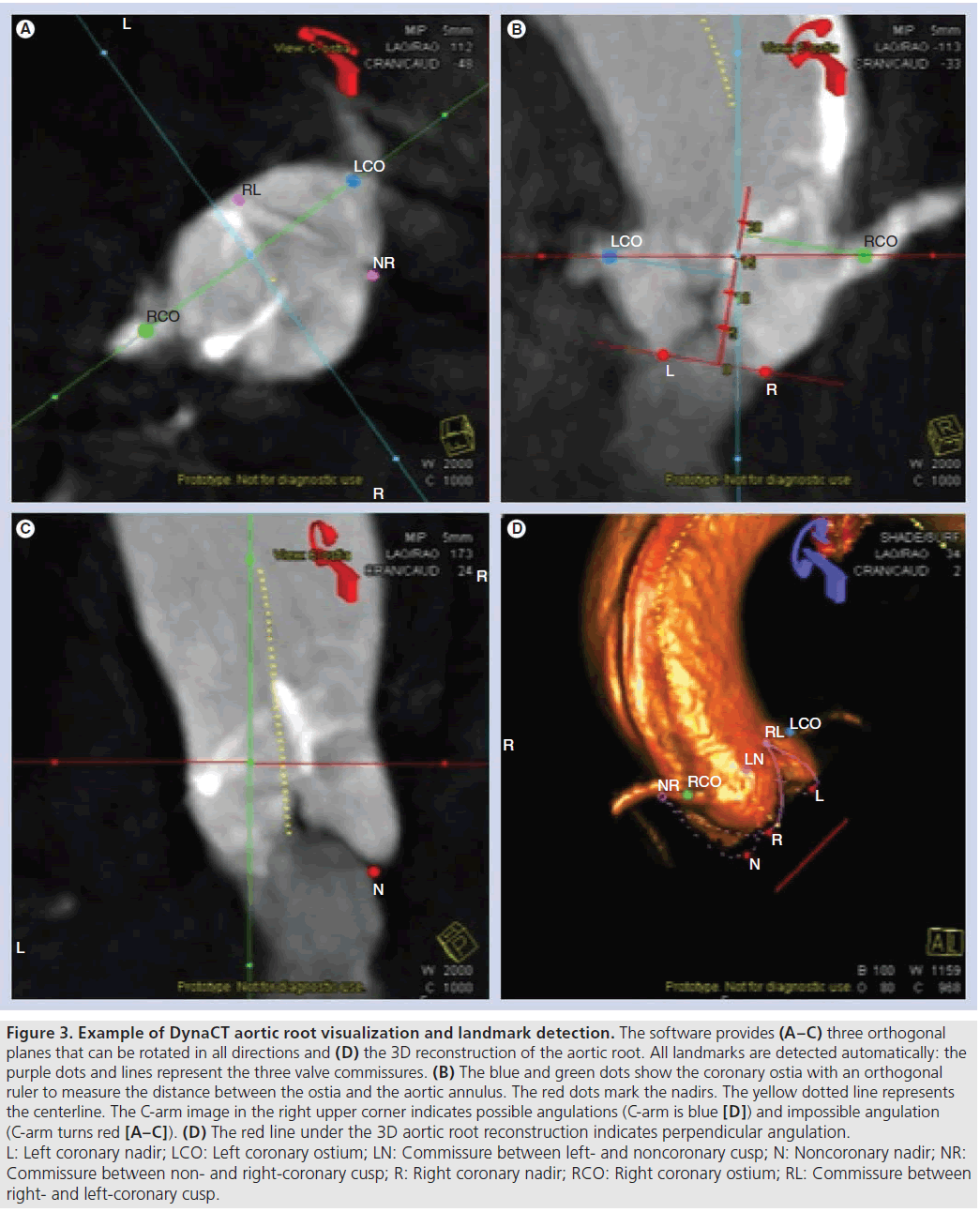
After rotational angiography, the acquired 2D images are automatically reconstructed to a 3D image of the aortic root. The workstation screen shows three orthogonal intersection planes and the 3D volume rendering (Figure 3). The software (Syngo Aortic ValveGuide, Siemens AG) offers some additional, automatically detected landmarks (Figure 3): the most caudal attachment of the three aortic valve leaflets (the three nadirs), the right and the left coronary ostium, the aortic valve commissures and a centerline through the ascending aorta. Based on these automatically detected landmarks, some additional information is projected on the 3D image. A red circle is shown below the aortic annulus that is based on the position of the three nadirs (most caudal attachment of the three native aortic cusps), which are quite consistent landmarks in the aortic root in many patients. This red circle is parallel to a plane of the three attachments of the aortic valve leaflets. By virtually adjusting the angulation of the 3D aortic root image, the red circle becomes a line when the three aortic valve leaflets are aligned, indicating a perpendicular view to the aortic root. Once the operator has assessed the correct perpendicular angulation, the C-arm can be rotated to this angulation by pushing one button. Another projected information is a ruler orthogonal to the plane of the three attachments of the aortic valve leaflets up to the automatically detected coronary ostia. This ruler allows the distance between the aortic annulus and the coronary ostia to be measured. All landmarks and information are shown in the orthogonal intersection planes, as well as in the 3D aortic root image. The landmarks are manually adjustable; if the operator finds the automatic detection imprecise they can be toggled on and off if displaying all landmarks is too confusing. The 3D image can be rotated to any angulation and an image of the patient table in the screen indicates whether the chosen angulation can be reached with the angio system (blue table indicates possible angulation, red table indicates impossible angulation [Figure 3]). Detailed information regarding the technical background and segmentation has previously been published [40,41].
Figure 3: Example of DynaCT aortic root visualization and landmark detection. The software provides (A–C) three orthogonal planes that can be rotated in all directions and (D) the 3D reconstruction of the aortic root. All landmarks are detected automatically: the purple dots and lines represent the three valve commissures. (B) The blue and green dots show the coronary ostia with an orthogonal ruler to measure the distance between the ostia and the aortic annulus. The red dots mark the nadirs. The yellow dotted line represents the centerline. The C-arm image in the right upper corner indicates possible angulations (C-arm is blue [D]) and impossible angulation (C-arm turns red [A–C]). (D) The red line under the 3D aortic root reconstruction indicates perpendicular angulation. L: Left coronary nadir; LCO: Left coronary ostium; LN: Commissure between left- and noncoronary cusp; N: Noncoronary nadir; NR: Commissure between non- and right-coronary cusp; R: Right coronary nadir; RCO: Right coronary ostium; RL: Commissure between right- and left-coronary cusp.
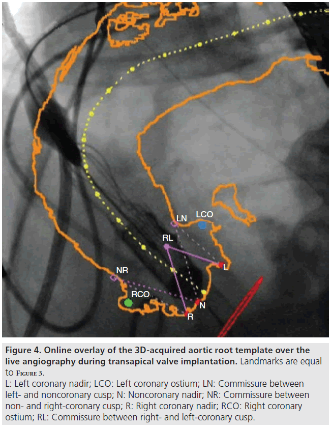
After checking all landmarks, the operator can switch to an online overlay of the aortic root to the live fluoroscopy screen (Figure 4). For online overlay the software offers a contour (circumferential) view and the contour is registered to fluoroscopy and it automatically adapts to C-arm and table movements. The overlay cannot adapt to patient movements leading to minor deviations in some cases. Manual adjustment of the overlay is possible.
Figure 4: Online overlay of the 3D-acquired aortic root template over the live angiography during transapical valve implantation. Landmarks are equal to Figure 3. L: Left coronary nadir; LCO: Left coronary ostium; LN: Commissure between left- and noncoronary cusp; N: Noncoronary nadir; NR: Commissure between non- and right-coronary cusp; R: Right coronary nadir; RCO: Right coronary ostium; RL: Commissure between right- and left-coronary cusp.
▪ Implementation of DynaCT in T-AVI workflow
Obviously, DynaCT has to be established in the routine workflow of the T-AVI procedure. Due to the rapid ventricular pacing protocol, it is actually performed under general anesthesia. For transfemoral AVI the best moment for DynaCT is after arterial puncture and placement of the pigtail catheter in the aortic root. During transapical AVI, DynaCT should be performed after opening of the pericardium and positioning of the pericardial stay sutures.
All members of the T-AVI-performing heart team including the anesthetist should know the key steps of DynaCT. The anesthesiological equipment such as TEE and respirator should be placed behind the patient’s head to avoid collision with the C-arm. After preparing the C-arm and the contrast pump, the surgeon or the cardiologist should give clear commands to the anesthetist to stop ventilation and start rapid ventricular pacing. When commencing using DynaCT these steps might take some time, but after the team becomes acquainted with DynaCT and once it is integrated into the routine workflow, it does not prolong the procedure because root angiographies do not have to be performed.
▪ Actual use of DynaCT during T-AVI Adjusting the perpendicular C-arm angulation during T-AVI
Application of contrast agent can lead to contrast-induced nephropathy, especially in the elderly high-risk T-AVI patient population [43]. Therefore, reducing the amount of contrast agent during T-AVI should be of special interest. The several root angiographies to find the perpendicular angulation for implantation take approximately 15 ml of contrast agent per root angiography. Depending on how fast the perpendicular angulation is found, this procedure can end up with a high amount of contrast agent. Since a complete DynaCT only requires 15 ml of contrast agent and the perpendicular angulation can easily be reached using the additional information of the red circle below the aortic annulus, a lot of contrast agent can be saved. Figure 3D shows a red line under the aortic root reconstruction, indicating a perpendicular view. If the angulation is not perpendicular, the line turns into a circle.
Valve positioning during T-AVI
The online overlay allows for better estimation of the prosthesis height in relation to the aortic annulus and especially in relation to the coronary arteries. This helps prevent coronary artery occlusion by the prosthesis and provides more precise implantation.
Anatomically correct rotation of any implanted prosthesis
The visualization of the native aortic valve commissures eases the implantation of some new-generation T-AVI prostheses that allow for anatomical orientation of the valve. The stent commissures of the prosthesis can be easily aligned with the commissures of the DynaCT image (Figure 4).
▪ Future perspectives of DynaCT during T-AVI
There are different aspects to focus further improvements of DynaCT imaging during T-AVI in the future: visualization and, later, measurements of the aortic annulus, similar to MSCT, will be feasible by additionally contrasting the left ventricle via a second pigtail in the ventricle during image acquisition. The automatic detection of the nadirs eases the location of the perfect aortic annular plane. The software will then allow for any aortic annulus measurements that are now performed in MSCT, such as measuring the ‘effective’ diameter.
Tracking will lead to a perfect online overlay mode of the DynaCT-acquired images during all phases of the heart beat: any patient movement and especially heart movement can influence the accuracy of the online overlay at present. There are efforts to implement a tracking tool. Potential tracking targets are the spine, the native calcifications of the aortic valve or aorta, the pigtail in the noncoronary cusp of the aortic root or insertion of the coronary arteries. With improved online overlay, DynaCT should lead to a very precise tool for correct implantation of the prosthesis.
Due to the motion artifacts the theoretically available image fusion with other imaging modalities is not yet available for DynaCT during T-AVI. Together with better tracking and by negotiating the motion artifacts, it will be possible to implement 2D and 3D real-time TEE into the DynaCT images.
Another future option will involve template planning, a virtual simulation of the different available valve prosthesis into the 3D aortic root image. With this tool it will be possible to simulate the position of the prosthesis inside the annulus and in relation to the coronary ostia. It will help to predict potential coronary occlusion by the prosthesis and will help to find a good prosthesis height inside the aortic annulus. In addition, it will aid the physicians in selecting the ideal prosthesis for an individual patient.
Current DynaCT does not allow for detection and quantification of aortic valve calcification. Due to the fact that the degree of calcification might play a major role in the occurrence of postoperative paravalvular aortic regurgitation [44,45], future generations of DynaCT will also offer measurement tools for the degree of aortic valve calcification.
With all these new options included in clinical use, DynaCT may alleviate the use of additional preoperative imaging techniques. At present is has already evolved as a valuable tool in routine clinical practice during T-AVI. Together with advanced T-AVI prostheses, DynaCT may replace the majority of preoperative imaging. The scenario might be like this: aortic stenosis is diagnosed in TTE. After surgical risk assessment and decision to undertake T-AVI, a coronary angiography is routinely performed to exclude significant coronary artery disease. During coronary angiography an injection of contrast agent into the abdominal aorta is performed to screen for severe kinking of the femoral arteries and to measure their diameter. No further imaging is necessary. The patient will be prepared for T-AVI and DynaCT is performed on the table. Aortic annulus diameter as well as coronary artery distance is measured and the decision for the most suitable valve prosthesis can be made immediately after DynaCT, similar to the decision-making during conventional aortic valve replacement. While preparing the chosen valve prosthesis, the T-AVI procedure continues in the usual fashion.
Financial & competing interests disclosure
G Nollert is an employee of Siemens. The authors have no other relevant affiliations or financial involvement with any organization or entity with a financial interest in or financial conflict with the subject matter or materials discussed in the manuscript apart from those disclosed.
No writing assistance was utilized in the production of this manuscript.
References
Papers of special note have been highlighted as:
▪ of interest
▪▪ of considerable interest
- Leon MB, Smith CR, Mack M et al. Transcatheter aortic-valve implantation for aortic stenosis in patients who cannot undergo surgery. N. Engl. J. Med. 363(17), 1597–1607 (2010).
- Smith CR, Leon MB, Mack MJ et al. Transcatheter versus surgical aortic-valve replacement in high-risk patients. N. Engl. J. Med. 364(23), 2187–2198 (2011).
- Pasic M, Buz S, Dreysse S et al. Transapical aortic valve implantation in 194 patients: problems, complications, and solutions. Ann. Thorac. Surg. 90(5), 1463–1469 (2010).
- Rodes-Cabau J, Webb JG, Cheung A et al. Transcatheter aortic valve implantation for the treatment of severe symptomatic aortic stenosis in patients at very high or prohibitive surgical risk: acute and late outcomes of the multicenter Canadian experience. J. Am. Coll. Cardiol. 55(11), 1080–1090 (2010).
- Walther T, Schuler G, Borger MA et al. Transapical aortic valve implantation in 100 consecutive patients: comparison to propensity-matched conventional aortic valve replacement. Eur. Heart J. 31(11), 1398–1403 (2010).
- Willson A, Toggweiler S, Webb JG. Transfemoral aortic valve replacement with the SAPIEN XT valve: step-by-step. Semin. Thorac. Cardiovasc. Surg. 23(1), 51–54(2011).
- Walther T, Mollmann H, Van Linden A, Kempfert J. Transcatheter aortic valve implantation transapical: step by step. Semin. Thorac. Cardiovasc. Surg. 23(1), 55–61(2011).
- Eker A, Sozzi FB, Civaia F, Bourlon F. Aortic annulus rupture during transcatheter aortic valve implantation: safe aortic root replacement. Eur. J. Cardiothorac. Surg.41(5), 1205 (2012).
- Gogas BD, Zacharoulis AA, Antoniadis AG. Acute coronary occlusion following TAVI. Catheter Cardiovasc. Interv. 77(3), 435–438(2011).
- Saia F, Marrozzini C, Marzocchi A. Displacement of calcium nodules of the native valve as a possible cause of left main occlusion following transcatheter aortic valve implantation. J. Invasive Cardiol. 23(5), e106–e109 (2011).
- Kempfert J, Walther T, Borger MA et al. Minimally invasive off-pump aortic valve implantation: the surgical safety net. Ann. Thorac. Surg. 86(5), 1665–1668 (2008).
- Walther T, Dewey T, Borger MA et al. Transapical aortic valve implantation: step by step. Ann. Thorac. Surg. 87(1), 276–283 (2009).
- Moss RR, Ivens E, Pasupati S et al. Role of echocardiography in percutaneous aortic valve implantation. JACC Cardiovasc. Imaging1(1), 15–24 (2008).
- Piazza N, De Jaegere P, Schultz C, Becker AE, Serruys PW, Anderson RH. Anatomy of the aortic valvar complex and its implications for transcatheter implantation of the aortic valve. Circ. Cardiovasc. Interv. 1(1), 74–81 (2008).
- Tops LF, Wood DA, Delgado V et al. Noninvasive evaluation of the aortic root with multislice computed tomography implications for transcatheter aortic valve replacement. JACC Cardiovasc. Imaging 1(3), 321–330 (2008).
- Doddamani S, Grushko MJ, Makaryus AN et al. Demonstration of left ventricularoutflow tract eccentricity by 64-slice multi-detector CT. Int. J. Cardiovasc. Imaging 25(2), 175–181 (2009).
- Willmann JK, Weishaupt D, Lachat M et al. Electrocardiographically gatedmulti-detector row CT for assessment of valvular morphology and calcification in aortic stenosis. Radiology 225(1), 120–128 (2002).
- Altiok E, Koos R, Schroder J et al. Comparison of two-dimensional and three-dimensional imaging techniques for measurement of aortic annulus diameters before transcatheter aortic valve implantation. Heart 97(19), 1578–1584 (2011).
- Janosi RA, Kahlert P, Plicht B et al. Measurement of the aortic annulus size by real-time three-dimensional transesophageal echocardiography. Minim. Invasive Ther. Allied Technol. 20(2), 85–94 (2011).
- Ng AC, Delgado V, Van Der Kley F et al. Comparison of aortic root dimensions and geometries before and after transcatheter aortic valve implantation by 2- and 3-dimensional transesophageal echocardiography and multislice computed tomography. Circ. Cardiovasc. Imaging 3(1), 94–102 (2010)
- Schultz CJ, Moelker A, Piazza N et al. Three dimensional evaluation of the aortic annulus using multislice computer tomography: are manufacturer’s guidelines for sizing for percutaneous aortic valve replacement helpful? Eur. Heart J. 31(7), 849–856 (2010).
- Blanke P, Siepe M, Reinohl J et al. Assessment of aortic annulus dimensions for Edwards SAPIEN Transapical Heart Valve implantation by computed tomography: calculating average diameter using a virtual ring method. Eur. J. Cardiothorac. Surg.38(6), 750–758 (2010).
- Kempfert J, Van Linden A, Lehmkuhl L et al. Aortic annulus sizing: echocardiographic vs. computed tomography derived measurements in comparison with direct surgical sizing. Eur. J. Cardiothorac. Surg. doi:10.1093/ejcts/ezs064 (2012) (Epub ahead of print)
- Kurra V, Kapadia SR, Tuzcu EM et al. Pre-procedural imaging of aortic root orientation and dimensions: comparison between x-ray angiographic planar imaging and 3-dimensional multidetector row computed tomography. JACC Cardiovasc. Interv. 3(1), 105–113 (2010).
- Mesa Rubio D, Suarez de Lezo Cruz Conde J, Alvarez-Osorio MP et al. Measurement of aortic valve annulus using different cardiac imaging techniques in transcatheter aortic valve implantation: agreement with finally implanted prosthesis size. Echocardiography 28(4), 388–396 (2011).
- Gurvitch R, Wood DA, Leipsic J et al. Multislice computed tomography for prediction of optimal angiographic deployment projections during transcatheter aortic valve implantation. JACC Cardiovasc. Interv. 3(11), 1157–1165 (2010).
- Gurvitch R, Wood DA, Leipsic J et al. Multislice computed tomography for prediction of optimal angiographic deployment projections during transcatheter aortic valve implantation. JACC Cardiovasc. Interv. 3(11), 1157–1165 (2010).
- Dumont E, Lemieux J, Doyle D, Rodes-Cabau J. Feasibility of transapical aortic valve implantation fully guided by transesophageal echocardiography. J. Thorac. Cardiovasc. Surg. 138(4), 1022–1024 (2009).
- Doelken M, Struffert T, Richter G et al. Flat-panel detector volumetric CT for visualization of subarachnoid hemorrhage and ventricles: preliminary results compared to conventional CT. Neuroradiology 50(6), 517–523 (2008).
- Heran NS, Song JK, Namba K, Smith W, Niimi Y, Berenstein A. The utility of DynaCT in neuroendovascular procedures. AJNR Am. J. Neuroradiol. 27(2), 330–332(2006).
- Eide KR, Odegard A, Myhre HO, Hatlinghus S, Haraldseth O. DynaCT in pre-treatment evaluation of aortic aneurysm before EVAR. Eur. J. Vasc. Endovasc. Surg. 42(3), 332–339(2011).
- Nordon IM, Hinchliffe RJ, Malkawi AH et al. Validation of DynaCT in the morphological assessment of abdominal aortic aneurysm for endovascular repair. J. Endovasc. Ther. 17(2), 183–189 (2010).
- Nolker G, Asbach S, Gutleben KJ et al. Image-integration of intraprocedural rotational angiography-based 3D reconstructions of left atrium and pulmonary veins into electroanatomical mapping: accuracy of a novel modality in atrial fibrillation ablation. J. Cardiovasc. Electrophysiol. 21(3), 278–283 (2010).
- Gutleben KJ, Nolker G, Ritscher G et al. Three-dimensional coronary sinus reconstruction-guided left ventricular lead implantation based on intraprocedural rotational angiography: a novel imaging modality in cardiac resynchronization device implantation. Europace 13(5), 675–682 (2011).
- Iampreechakul P, Chongchokdee C, Tirakotai W. The accuracy of computer-assisted pedicle screw placement in degenerative lumbrosacral spine using single-time, paired point registration alone technique combined with the surgeon’s experience. J. Med. Assoc. Thai. 94(3), 337–345 (2011).
- Kempfert J, Noettling A, John M, Rastan A, Mohr FW, Walther T. Automatically segmented DynaCT: enhanced imaging during transcatheter aortic valve implantation. J. Am. Coll. Cardiol. 58(25), e211 (2011).
- Karar ME, Gessat M, Walther T, Falk V, Burgert O. Towards a new image guidance system for assisting transapical minimally invasive aortic valve implantation. Conf. Proc. IEEE Eng. Med. Biol. Soc. 2009,3645–3648 (2009).
- Kempfert J, Falk V, Schuler G et al. DynaCT during minimally invasive off-pump transapical aortic valve implantation. Ann. Thorac. Surg. 88(6), 2041 (2009).
- Schwartz JG, Neubauer AM, Fagan TE, Noordhoek NJ, Grass M, Carroll JD. Potential role of three-dimensional rotational angiography and C-arm CT for valvular repair and implantation. Int.J. Cardiovasc. Imaging 27(8), 1205–1222(2011).
- John M, Liao R, Zheng Y et al. System to guide transcatheter aortic valve implantations based on interventional C-arm CT imaging. Med. Image Comput. Comput. Assist. Interv. 13(Pt 1), 375–382 (2010).
- Zheng Y, John M, Liao R et al. Automatic aorta segmentation and valve landmark detection in C-arm CT: application to aortic valve implantation. Med. Image Comput. Comput. Assist. Interv. 13(Pt 1), 476–483(2010).
- Bai M, Liu B, Mu H, Liu X, Jiang Y. The comparison of radiation dose between C-arm flat-detector CT (DynaCT) and multi-slice CT (MSCT): a phantom study. Eur. J. Radiol. doi.org/10.1016/ j.ejrad.2011.09.006 (2011) (Epub ahead of print).
- Van Linden A, Kempfert J, Rastan AJ et al. Risk of acute kidney injury after minimally invasive transapical aortic valve implantation in 270 patients. Eur. J. Cardiothorac. Surg.39(6), 835–842 (2011).
- John D, Buellesfeld L, Yuecel S et al. Correlation of device landing zone calcification and acute procedural success in patients undergoing transcatheter aortic valve implantations with the self-expanding CoreValve prosthesis. JACC Cardiovasc. Interv. 3(2), 233–243 (2010).
- Ewe SH, Ng AC, Schuijf JD et al. Location and severity of aortic valve calcium and implications for aortic regurgitation after transcatheter aortic valve implantation. Am. J. Cardiol. 108(10), 1470–1477 (2011).
▪▪ Large, randomized transcatheter aortic valve implantation (T-AVI) trial for FDA approval.
▪▪ Large, randomized T-AVI trial for FDA approval.
▪ Detailed step-by-step description of transfemoral AVI and transapical AVI.
▪ Detailed step-by-step description of transfemoral AVI and transapical AVI.
▪ Good evaluation of multislice computed tomography for T-AVI.
▪▪ First imaging-based annulus sizing compared with in vivo/intraoperative sizing.
▪ The impact of intraoperative contrast agent dose on renal function.
